This thread has been locked.

If you have a related question, please click the "Ask a related question" button in the top right corner. The newly created question will be automatically linked to this question.

ezDSP 5535

Hi all,

I'm facing some unexpected issues with a ezdsp5535 that I recently purchased and I hope that someone here might have some help to provide.

I performed the normal CCS4 install (under windows 8 Pro), without the board plugged in and everthing gone perfect. I installed the board drivers and got the demo to work while connecting through J1 perfectly.

However, when I plugg through J2 and try to do some testing using custom code (for example lcd-osd9616) at connection time with the target I get the following error message:

C55xx: Error connecting to the target: (Error -151 @ 0x0) This utility failed to open the adapter for a custom emulator. The adapter returned an error. (Release 5.0.429.0)

I did my setup using TI XDS100v2 USB Emu and EZDSP5535 device. Just to specify that I also have a ezdsp5515 finger print DK, I can perfectly connect and debug with. Also, I tried the install on a Win7 computer with no more luck (as a sanity check for win8 potential issues)

As additional details, the board is recognized in the driver manager as:

- Ports (Com and LPT) --> USB Serial Port (COM7and COM8)

- Universal Serial bus controllers --> USB Serial Converter (A and B)

Which sounds weird to me as I would be expecting TI XDS100 Channel (A and B) in universal.

I spent hours on it already and would greatly appreciate any help before I throw the kit through my window ;-) Kinding but noot that much.

Thank you a lot!

Sincerely,

Jean-Christophe

  • All right people,

    It proves that sometimes, just explaining your issues to others help you a lot.

    It looks like the FTDI was not programmed when I recieved my board. So, others that might face similar issues in the future:

    - Check in your windows device manager. If you see that the J2 plug is recognized as a USB Serial Converter --> That's your issue

    Solve it by using MProg3.5 and Flash your VID-PID.

    Everything is well explained and can be followed in the following TI link @ the Hardware FAQ:   http://processors.wiki.ti.com/index.php/XDS100

    I do not see how I could have erased my EEPROM myself, so please people from Spectrum Digital --> Add some controls in your process!

    But your products are great all in all so no anger.

    Thanks,

    Jean-Christophe

  • Thank you Jean-Christophe!

    I had the same problem, and solved it with your suggestion.  My FTDI chip wasn't erased, but it did indeed have the wrong code programmed into it (PID=6010, like the wiki example).

    Incidentally, the little Quick-Start hardcopy that come with the Spectrum Digital eZdsp board was missing the 7th page (sections 6.5 through 6.8 are missing).  This was not obvious.  The included pdf is correct.

    Mike Helmig

  • Your welcome,

    Glad it could help!

    Jean

  • Hi,

    im having the same issue.
    What do you mean bly "Solve it by using MProg3.5 and Flash your VID-PID." I am a total noob here and need some serious help.
    Basically, the XDS emulator is not appearing in my device manager when I plug in the ezdsp through port J2. Not sure at all what to do.

    Thanks for any help,
    nate 

  • Hi Nate,

    Well no sweat, it should be easy.

    When you plug your dev kit (! be sure you are connecting it through J2, which is the port for the xds100 emulator) you should look into your win Dev manager and look into (edit):

    -Universal Serial Bus Controllers

    and should see TI XDS100 Channels A and B

    If not, download FTD2XXST (Ignore MProg which is obsolet looks like (but it should work anyway)) tool here:

    http://www.ftdichip.com/Support/Utilities.htm#FTD2XXST

    FTD2XXST  is just a tool which will help you write the EEPROM of the FTDI. So gues what, you need the image of the emulator!

    here: http://processors.wiki.ti.com/images/0/00/XDS100_wUART.zip

    Comments: It is recommanded you flash FTDI with a XDS100v2, even if on the hardware prospective ezdsp does not make use of the EMU pins, so it will not make any differences.

    All credits to: http://processors.wiki.ti.com/index.php/XDS100

    Dig into it for the rest.

    Good luck,

    JC

  • Thanks for response JC,

    Im going to try the steps outlined in :

    Q: How do I reprogram the VID/PID EEPROM if it has not been programmed correctly?

    at this link: http://processors.wiki.ti.com/index.php/XDS100#Q:_How_can_I_check_if_the_VID.2FPID_for_the_EEPROM_are_programmed_correctly.3F

     as I believe that is what you are suggesting I do. I will report back my results shortly!

    Thanks,

    Nate 

  • Hi JC, 

    Following the instructions given in the XDS100 Wiki to reprogram the EEPROM did NOT work. Ill show you through a series of screenshots what happened. This is what I did.
    0) I plugged in my eZdsp through the J2 port into my USB port on my computer. 
    1) I downloaded MProg3.5 .zip, unpacked and installed it. 

    2) I downloaded the XDS100_wUART.zip and unpacked it.
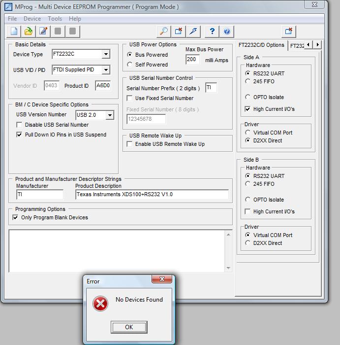
    3) I opened MProg3.5, and within the program opened the  XDS100_wUART.ept
    4) I scanned for available devices and got this:
      

    5) Then I erased the EEPROM by using ctrl+e and I got this:
      

    6) Then I tried to program the EEPROM using ctrl+p and i got this:
      

    It says no devices found. Anyone know how to help? Im totally stuck :(

    Thanks,
    Nate 

  • Update:

    I fixed the problem!
    Note to all future eZDSP C5535 Users:
    If you are having the same problem I am or just want to reprogram the EEPROM from Spectrum Digital - 
    Follow the steps outlined in :
    http://processors.wiki.ti.com/index.php/XDS100#Q:_How_do_I_reprogram_the_VID.2FPID_EEPROM_if_it_has_not_been_programmed_correctly.3F

    But instead of using the XDS100_wUART.ept to program the EEPROM (like the WIKI tells you to do in step #2), use the XDS100_wUART_FT2232H.ept file downloadable here:
    http://processors.wiki.ti.com/images/f/f8/XDS100_wUART_FT2232H.zip

    it worked for me. The EEPROM was succesfully programmed, and the proper VID and PID (VID=0403 PID=A6D1) #'s appear. 

    Thanks again,
    Nate 

  • Nate,

    I feel closer and closer to the solution to these endless woes with every one of your posts! I tried the XDS100_wUART_FT2232H.ept file too, but no luck. Actually, when I go to Device->Scan, MProg comes back with:

    Number Of Blank Devices = 0

    Number Of Programmed Devices = 0

    I tried different ports, but it doesn't detect that my eZdsp C5535 is even plugged in. Does any of this sound familiar?

    Thanks for any help!

  • Are you plugging the ezdsp board into your computer through the USB emulation connector (J2 - the bigger USB port that plugs directly into your computer)? Do not use the smaller J1 microUSB port - that is not used for emulation. Let me know if that was the issue.

    - Nate 

  • It works! I got the LED test  running. And yes, it was the wrong port. Now I have to try the other tests like the OLED. This thing is buggy as all outdoors though. It has frozen on me and I had to restart it about 6-7 times so far! To clear one program and upload a whole new program to hardware, do you just do an emulator reset?

  • You remind me of me 3 months ago! Had all the same problems :)
    Once you enter debug mode (which automatically "connects you to the target") you can load programs and run them. If you want to rerun it, do a restart (which depending on your GEL may reset peripherals and put the program counter back to the start of main), or a reload program command (which does stuff depending on your GEL file). If you want to edit code and then try it out, pause the emulation, edit your code, save, and reload the program. Once I enter debug mode, I rarely leave it because it takes forever to enter it and there is no need to leave and re-enter. 
    If you need help with GEL files, let me know I have a document that might help you :)


  • Thanks! you're awesome!

    Actually, I'm an engineer, but I've never gotten near DSP except for an undergrad class years ago. At this point, I need to learn how to even begin coding a proper DSP routine at all. If you know of any document that focuses specifically on this unit and presents examples of startup projects using the analog stereo input and output, that would be the best thing. I remember all the basics about how to program an FFT and use of correlation  and convolution, etc, but this has a library that handles all that stuff, so at this point, I just need basic things that I can pick apart to learn the firmware and hardware functionality. I've issued a request to TI University for the Teaching C5535 CD ROM, but since I can't find it anywhere safe for download, I fear it may no longer be in circulation.

    Thanks again for your patience!

  • Hmm for examples of projects - I would google "C5500 Teaching ROM," order the CD (its free from the TI website) and then use the wiki page called Porting the C5500 Teaching ROm to C5535" and follow the steps there. I received the teaching ROM when I ordered it from TI 3 months ago so I think it's still available. The teaching ROM is cool, but I would recommend studying it and writing your own code. Also the teaching ROM has nothing on taking an FFT - only real time inter-sample processing, if you know what I mean. To do FFT's in real time, you need to set up the DMA, and whoo that can be a pain. There is a DSP library for the C55xx, so download that. Also you can program peripherals using the CSL (Chip support library - high level functions for setting up peripherals) and using register level programming. I had more success with register level programming. 
    Anyway I had a long uphill frustrating battle making my project work, so hopefully I can help others like you out and save you some headache. 

    - Nate