I've got a A/D converter connected to a DSP6747 device (B; Rev. 2.0), configured to asynchronous R/W, CS4
At some point I wondered why my interrupt routine accessing this converter at 500kHz consumes such CPU load.
Some data on the configuration:
100 MHz bus clock (confirmed on pin), 300 MHz DSP clock (consistent with NOP delay time)
CS4 with 1-3-1- timing, WAIT disabled, normal mode
No SDRAM or Flash at this interface
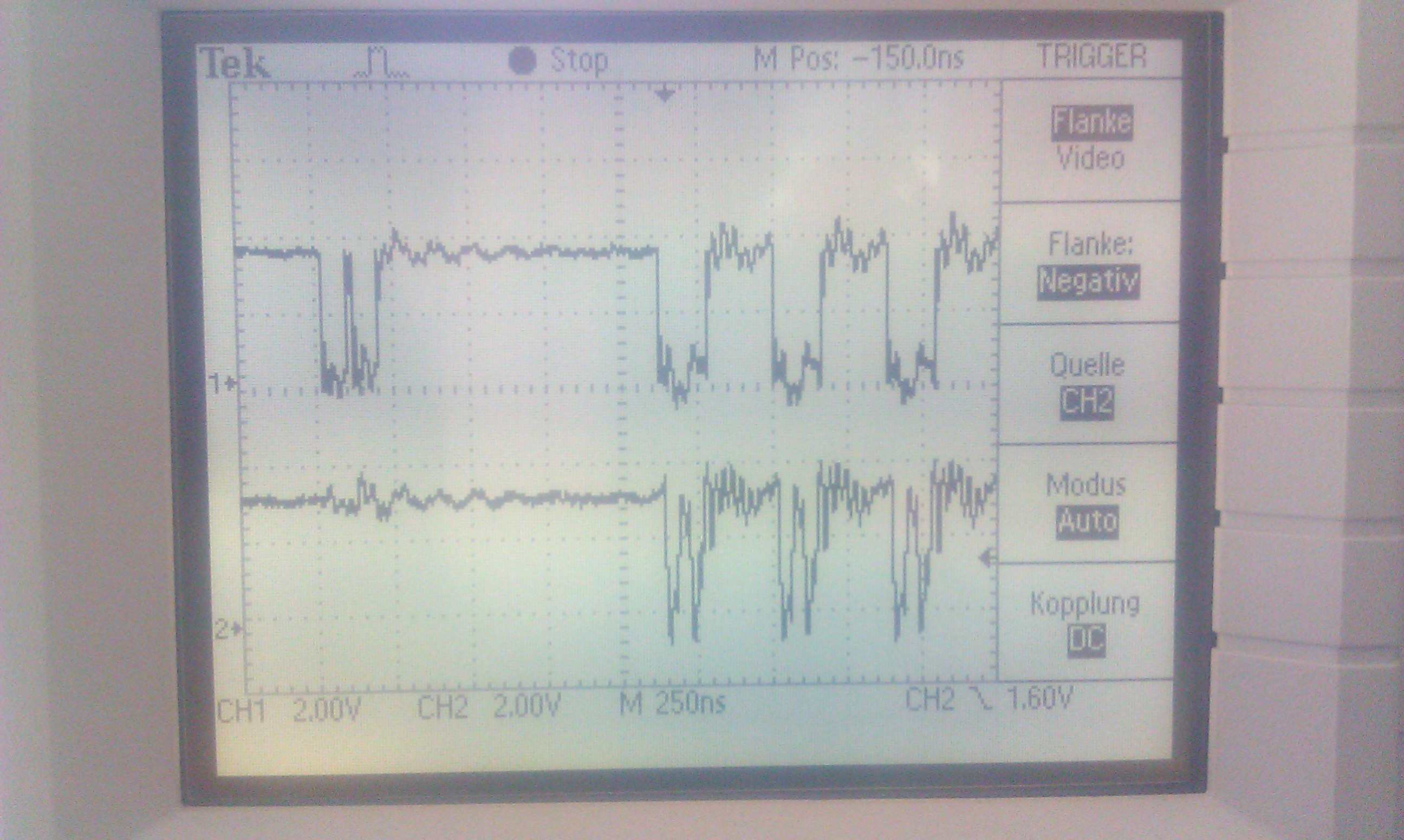
The answer came looking at the bus with an oszilloscope within a simple test: endless loop with 16 or 32 bit accesses to the interface (6 accesses within the loop, no asm instruction between the 6 reads/writes).
every read access is followed by 200 ns to 220ns of silence on the bus, basically:
16 bit read: CS low -> 10ns later OE low -> 30ns later OE back -> 10ns later CS high -> 220ns break!!! -> CS low ...
32 bit read: CS low -> 10ns later OE low -> 30ns later OE back -> 20ns later OE low-> 30ns later OE back -> 10ns later CS high -> 220ns break!!! -> CS low ...
The funny thing: write accesses are not affected!
16 bit write: CS low -> 10ns later WR low -> 30ns later WR back -> 10ns later CS high -> 20ns break -> CS low ...
32 bit read: CS low -> 10ns later WR low -> 30ns later WR back -> 20ns later WR low-> 30ns later WR back -> 10ns later CS high -> 20ns break -> CS low ...
Something inserts a 200ns delay after each read access. I checked, as far as I could, all possibilities:
NAND is disabled
WAIT is disabled
EMIFA powerdown is disabled
Power controller? Would probably switch the whole thing off completely...
Bandwidth controller? But there are nothing but L1PRAM accesses and EMIFA.
Asynchronous bridge? OK, some delay but 200ns for a 300MHz / 100MHz bridge?
Error Registers? empty!
Interrupts? Disabled except NMI
The impact of this effect is severe! A connected ADS8556 cannot be read within the timeframe between two conversions (700ns @ 500kHz), reading these values takes 800ns and therefore 40% CPU load!!!
btw: sampling the same asynchronous peripheral by DMA, I can confirm the same "turnaround" time as found here http://e2e.ti.com/support/dsp/omap_applications_processors/f/42/t/199192.aspx
Also looking through the posts, in http://e2e.ti.com/support/dsp/omap_applications_processors/f/42/t/193033.aspx within the screenshot the first 2 µs before the interrupt, that looks very familiar. Read after write follows 'immediately', but after a read there are 200ns delay before the next write.
Additional information:
-> Address range not cached!
-> EDMA has a delay of 8 bus cycles between two "reads", CPU access 20-22
-> read after write follows according to turnaround time, write after read after the 200ns @ 100 MHz (CPU access)
-> all other timings follow the CE4CFG register settings
-> same problem with CE5 and when mixing CE3 / CE4 / CE5 access (no device connected)
-> doesn't matter if same, consecutive of completely different address within read access
-> PSC on always on
-> Busclock out on scope without interruption
-> AWCC MAX_WAIT or PMCR CSx_PG_DEL values have no influence
-> code in L1PRAM or L2RAM(->L1P by caching ), doesn't matter
-> Writing read values to L1DRAM or EMIFB (write cache?), also no change