This thread has been locked.

If you have a related question, please click the "Ask a related question" button in the top right corner. The newly created question will be automatically linked to this question.

LCD ( ILI9486 Panel) initial code question

Hi~~

The Develop Platform is PandaBoard ( OMAP4460 )

I have a question about sending initial code to Panel.

according to ILI9486 Panel SPEC ( IM0=0 IM1=0 IM2=0 Mode=8080 18-bit bus interface DB[17:0] ) 

We need to send some initial code for panel through DB[0:17] haven't use SPI interface.

My question is that how to set command and parameter to DB[0:17] on Panda board?? (I have modify panel-generic-dpi.c) 

IM2 IM1 IM0 MPU-Interface Mode WRX RDX D/CX Function
0 0 0 Rising H L Write Commad Code
8080 MCU 18-bit bus interface  H Rising H Read internal status
Rising H H Write parameter or display data. 
H Rising H Reads parameter or display data

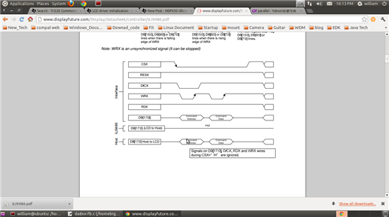
Here is the timing for write and read data  

Could you give us some sample code about initial ILI9486 panel?? 

EX: command 29h                                  D/CX = 0  DB[0:17] = 00101001

       command 51h parameter FFh         D/CX =0  DB[0:17] = 01010001            D/CX =1    DB[0:17] = 11111111

      .............

thanks your support.

  • You wouldn't want to modify panel-generic-dpi.

    Normally these init commands are done in the panel driver's init function. We wouldn't have any sample code for that particular panel. This is a DPI panel?

    DPI panels can only be used on LCD2. LCD1 is DSI or RFBI only.

    Matt 

  • As Matt said, it is better if you start a separate driver from panel-generic-dpi and just create a custom initialization function within this new driver. However, your new driver should look pretty similar to what panel-generic-dpi driver does.

    I don't see why you are not using SPI 4-line interface instead of the 8080 MCU interface for sending commands to the panel?? This should be much easier since OMAP4 already has SPI support. For a reference driver using SPI interface, refer to $kernel_path/drivers/net/ks8851.c (Ethernet Network driver) that is working on both Blaze and BlazeTablet. Take a look for ks8851 configuration on the corresponding board file as well ($kernel_path/arch/arm/mach-omap2/board-4430sdp.c for Blaze, $kernel_path/arch/arm/mach-omap2/board-44xx-tablet.c for BlazeTablet). If you still want to use 8080 MCU Interface, then most probably you would need to configure a set of GPIOs and program the logic on the driver which might  be much harder.

    For sending pixel data to the panel, seems like one of the important things you need to configure on this initialization function is to set your panel on RGB Interface mode (RGB 18-bit, 16-bit?) - this is the DPI interface. As Matt mentioned as well, you need it to be attached to LCD2. Since it is not a 24-bit DPI interface as typically configured, you would also need to configure the OMAP4 Display Controller to output 18-bit format instead.

  • Dear Bustamante

    Could you give us some suggestion about that We haven't seem any frame on panel , but have blink situation(Black ,Gray and red color).

    1. I have wrote new driver for ILI9486 panel , use 4 Line SPI mode to send initial code, It's workable.
    2. Driver  is enable successful. Signal is correct in scope. ( VSYNC  HSYNC PixelClock   DE )
    3. Add new dss device structure on board file.


    struct omap_dss_device omap4_panda_dvi_device = {
     .type   = OMAP_DISPLAY_TYPE_DPI,
     .name   = "dvi",
     .driver_name  = "ili9486_dpi_panel",
     .data   = &omap4_dvi_panel,
     .phy.dpi.data_lines = 18,
     .reset_gpio  = PANDA_DVI_ILI9486_GPIO,
     .channel  = OMAP_DSS_CHANNEL_LCD2,
    };


    /* Panel configurations */
    static struct panel_config generic_dpi_panels[] = {
     
     /* ILI 9486 */
     {
      {
       .x_res  = 320,
       .y_res  = 480,

       .pixel_clock = 12500,

       .hsw  =3,
       .hfp  =3,
       .hbp  = 3,
       
       .vsw  = 2,
       .vfp  = 2,
       .vbp  = 2,

      },
      .acbi   = 0x0,
      .acb   = 0x0,
      .config   = OMAP_DSS_LCD_TFT | OMAP_DSS_LCD_IVS |
           OMAP_DSS_LCD_IHS | OMAP_DSS_LCD_IEO,
      .power_on_delay  = 0,
      .power_off_delay = 0,
      .name   = "ili9486",
     },
    };


    Parameters                                 Symbols            Min.          Typ.            Max.                Units

     Horizontal Synchronization          Hsync                 3               3                -                     PCLK

    Horizontal Back Porch                  HBP                   3                3               -                      PCLK

    Horizontal Address                       HAdr                 -                  320           -                      PCLK

    Horizontal Front Porch                 HFP                   3                3                 -                      PCLK

    Vertical Synchronization               Vsync               2                     2             -                       Line

    Vertical Back Porch                      VBP                   2                    2              -                        Line

    Vertical Address                            VAdr                  -                   480           -                        Line

    Vertical Front Porch                      VFP                   2                    2             -                         Line

    Vertical Frequency(*)                                              50                 60            80                      Hz

    Horizontal Frequency(*)                                           -                   33             -                         KHz

    PCLK Frequency(*)                                                 10               12.5            15                      MHz


    Thanks your support

  • It's workable.

    Panel register setting incorrect.

    we have modify it and workable.

    Thanks you.


  • Dear William

    I have your same problems using ILI9486 panel

    You wrote " 1.I have wrote new driver for ILI9486 panel , use 4 Line SPI mode to send initial code, It's workable."

    Simply I do not understand if you use a standard OMAP 4wire SPI or have use 4 GPIO for reconstruct the signals needed to drive the LCD driver?

    I think the second method.

    Many Thanks

    Mirco