This thread has been locked.

If you have a related question, please click the "Ask a related question" button in the top right corner. The newly created question will be automatically linked to this question.

DM3730

Other Parts Discussed in Thread: DM3730

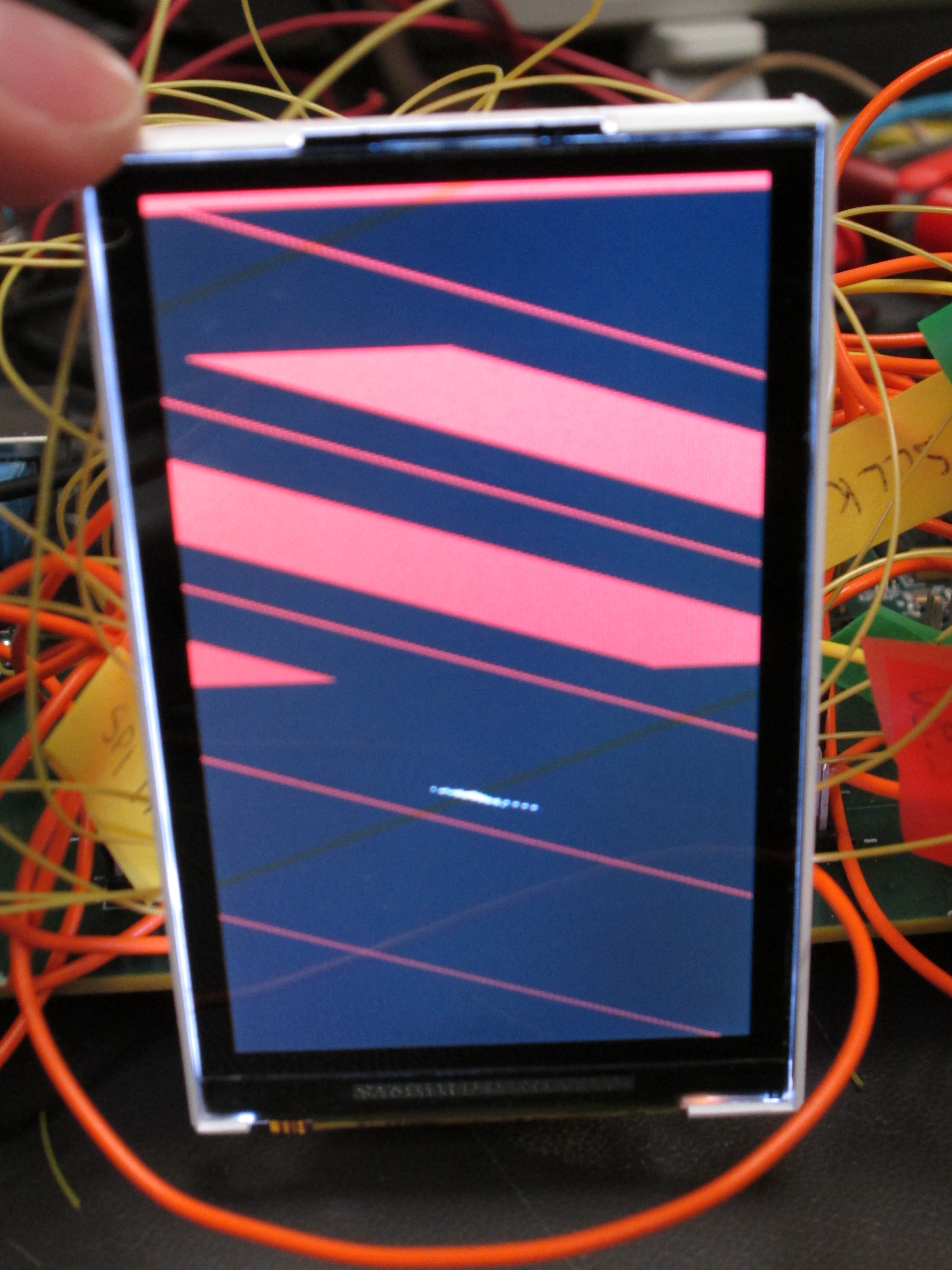
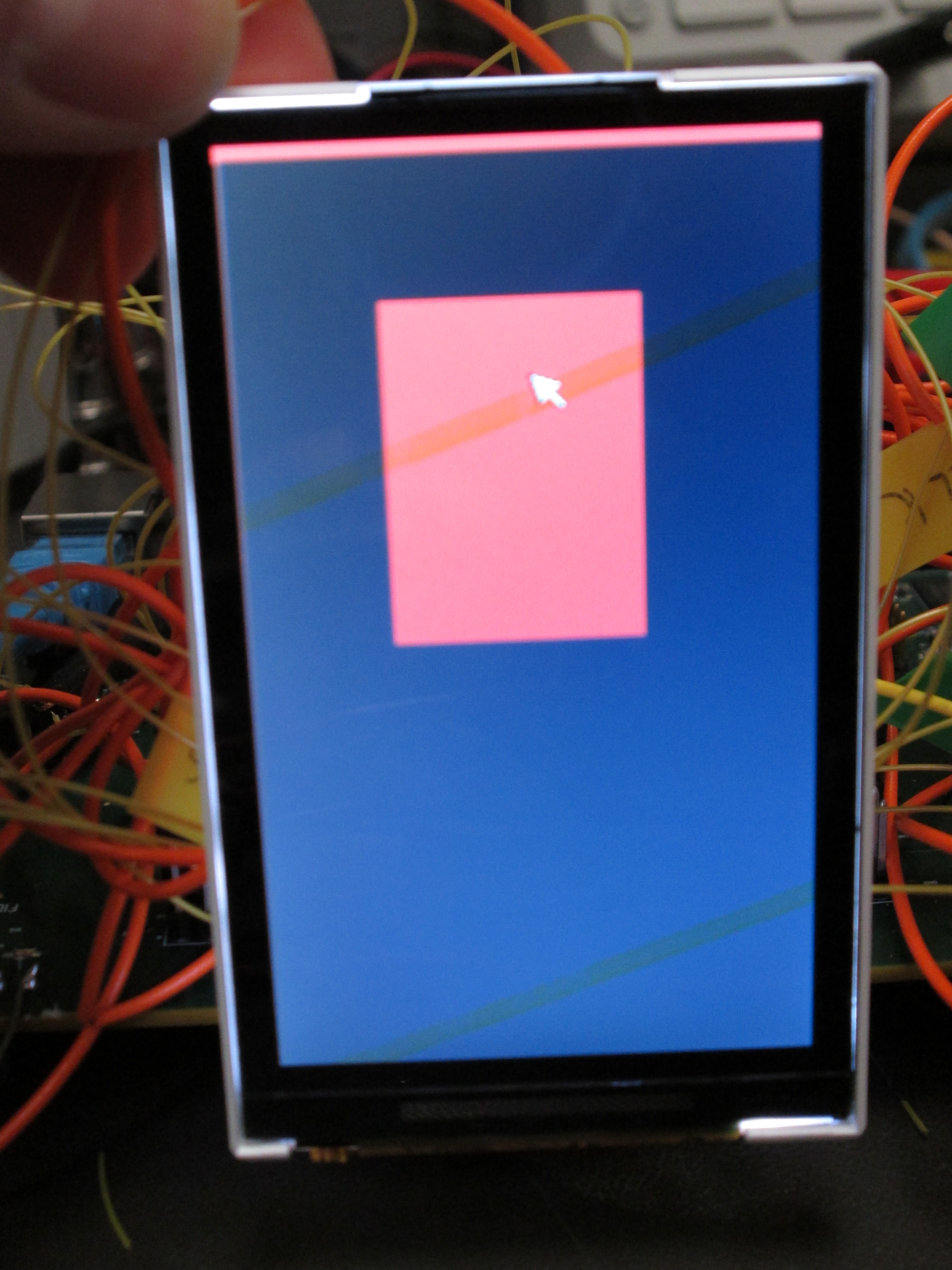
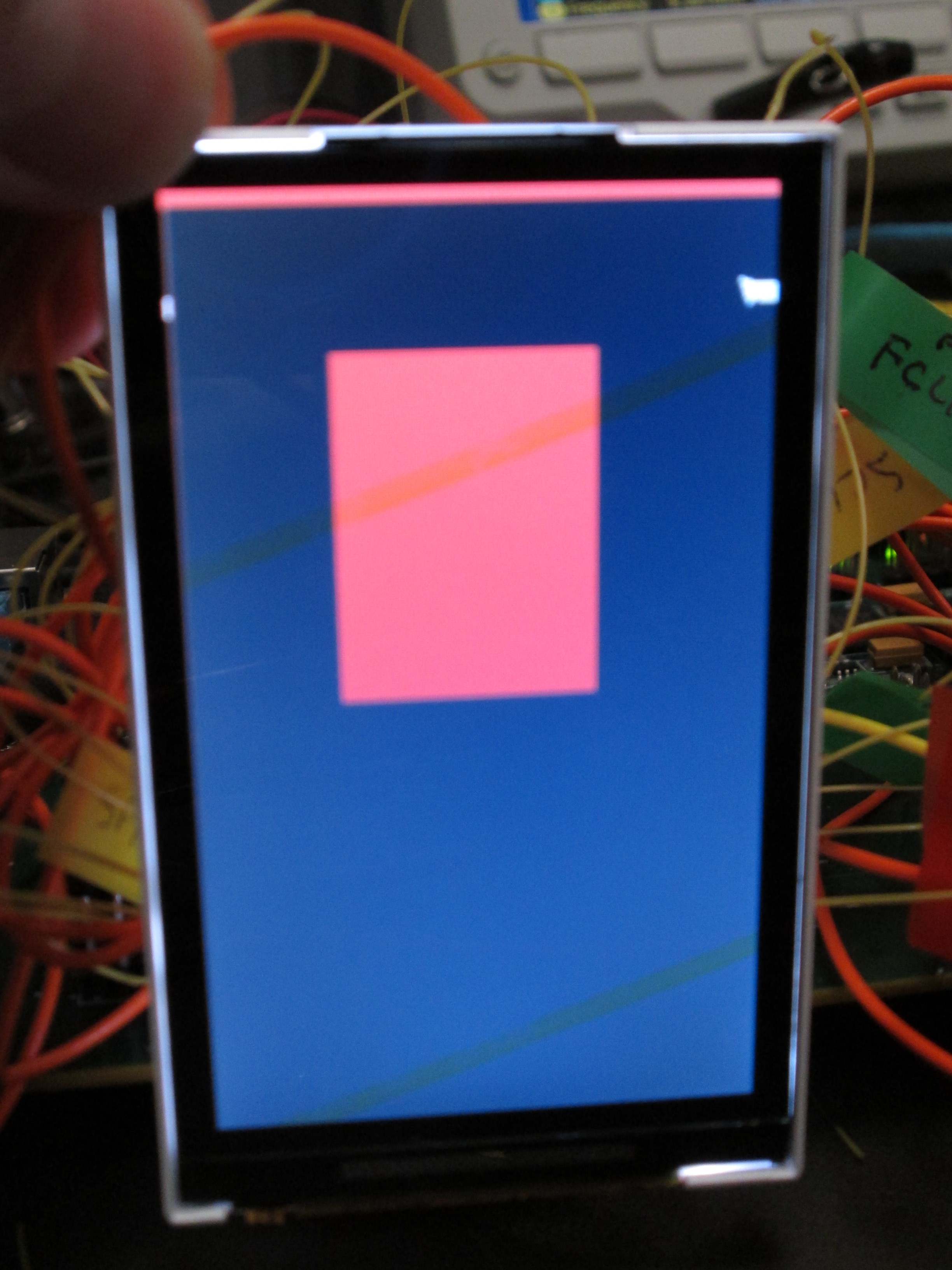
I have a GUMSTIX Overo Fire (GUM3503F) with the TI DM3730 MPU driving a Kyocera T-55149 240x400 LCD.  For some reason when the linux panel configuration (panel-generic-dpi.c) is set up with .x_res =240, .y_res=400, .pixel_clock=9200, .hfp=1, .hsw=1, .hbp=1, .vfp=2, .vsw=1, .vbp=4, an extra 4 pixels of data is fed to the LCD.  I check with an oscilloscope and the image gets cummulatively skewed by 4 pixels on every line.  This means that although I set up the TI processor for 240x400, actually 244x400 is output.  Even if i configure the panel to be 232x400, I can see that 4 extra pixel clocks are added to the output.  Why is this happening?

  • Victor,

    Are you sure that its getting skewed and not getting shifted? Can you dump the DISPC registers and send? If possible can you share an image?

  • Is there an easy way to dump the DISPC registers via Linux?  When I use mmap(...) and try to read consecutive registers, certain registers reads will result in "Unhandled fault: external abort on non-linefetch (0x1018) at 0xXXXXXXXX

  • There is a utility called "devmem2". Try it, you can pass a physical address from user space and read the values. Also you can write from user space.

  • This is what I use to attempt to read the values.  I had to put in quite a few address exclusions because the read fails.  Is this because the register does not exist?  For instance, if you execute "devmem2 0x48050404"  you will get "Unhandled fault: external abort on non-linefetch (0x1018) at 0xXXXXXXXX Bus error"

  •  


    Driver is configured 240x400

    Image:

     Oscilloscope Capture:

    The pixel clock is 9.29 MHz.  Oscilloscope shows the horizontal sync frequency to be 38.23 kHz.  This seems to indicate that 9.39 MHz/38.23 kHz = 243 pixels of data drives display.  So data is cummulatively shifted by 3 on every line.

    0143.tek240x400.tif


    Register Dump:

    root@overo:/opt/TestMobile1/bin# cat TIreg240x400.txt
    /dev/mem opened.
    Memory mapped at address 0x401d7000.
    Value at address 0x48050400: 0x30
    Value at address 0x48050410: 0x2015
    Value at address 0x48050414: 0x1
    Value at address 0x48050418: 0xA2
    Value at address 0x4805041C: 0xD640
    Value at address 0x48050440: 0x18309
    Value at address 0x48050444: 0x204
    Value at address 0x48050448: 0x3FF
    Value at address 0x4805044C: 0x0
    Value at address 0x48050450: 0x0
    Value at address 0x48050454: 0x0
    Value at address 0x48050458: 0x0
    Value at address 0x4805045C: 0x126
    Value at address 0x48050460: 0x0
    Value at address 0x48050464: 0x0
    Value at address 0x48050468: 0x400200
    Value at address 0x4805046C: 0x7000
    Value at address 0x48050470: 0x10003
    Value at address 0x48050474: 0xFF
    Value at address 0x48050478: 0x0
    Value at address 0x4805047C: 0x18F00EF
    Value at address 0x48050480: 0x9F400000
    Value at address 0x48050484: 0x9F400000
    Value at address 0x48050488: 0x0
    Value at address 0x4805048C: 0x18F00EF
    Value at address 0x480504A0: 0x91
    Value at address 0x480504A4: 0x3FF03C0
    Value at address 0x480504A8: 0x400
    Value at address 0x480504AC: 0x1
    Value at address 0x480504B0: 0x1
    Value at address 0x480504B4: 0x0
    Value at address 0x480504B8: 0x0


    Driver is configured 232x400

    Image:


    Image with arrow cursor to the right:


    Oscilloscope Capture:

    The pixel clock is 9.29 MHz.  Oscilloscope shows the horizontal sync frequency to be 38.71 kHz.  This seems to indicate that 9.39 MHz/38.71 kHz = 240 pixels of data drives display.  Picture looks perfect except the repeat data on the right side as show when the arrow cursor is moved to the right edge.  This is probably due to the front porch.  However, 3 pixels of data is still being added to each line 240 (Kyocera LCD width) - 232 pixels of data - 5 front porch clocks = 3 pixels per line. I would like to understand where the 3 extra pixels is coming from.

    2350.tek232x400.tif


    Register Dump:

     root@overo:/opt/TestMobile1/bin# cat TIreg232x400.txt
    /dev/mem opened.
    Memory mapped at address 0x40048000.
    Value at address 0x48050400: 0x30
    Value at address 0x48050410: 0x2015
    Value at address 0x48050414: 0x1
    Value at address 0x48050418: 0xA2
    Value at address 0x4805041C: 0xD640
    Value at address 0x48050440: 0x18309
    Value at address 0x48050444: 0x204
    Value at address 0x48050448: 0x3FF
    Value at address 0x4805044C: 0x0
    Value at address 0x48050450: 0x0
    Value at address 0x48050454: 0x0
    Value at address 0x48050458: 0x0
    Value at address 0x4805045C: 0x2C
    Value at address 0x48050460: 0x0
    Value at address 0x48050464: 0x500
    Value at address 0x48050468: 0x400200
    Value at address 0x4805046C: 0x7000
    Value at address 0x48050470: 0x10003
    Value at address 0x48050474: 0xFF
    Value at address 0x48050478: 0x0
    Value at address 0x4805047C: 0x18F00E7
    Value at address 0x48050480: 0x9F400000
    Value at address 0x48050484: 0x9F400000
    Value at address 0x48050488: 0x0
    Value at address 0x4805048C: 0x18F00E7
    Value at address 0x480504A0: 0x91
    Value at address 0x480504A4: 0x3FF03C0
    Value at address 0x480504A8: 0x400
    Value at address 0x480504AC: 0x1
    Value at address 0x480504B0: 0x1
    Value at address 0x480504B4: 0x0
    Value at address 0x480504B8: 0x0

  • Forgot to post the raw test image

    Test Image

  • Victor,

    Give me some time. I'll analyze the values and get back to you in couple of days.

  • Victor,

    Can you send me the panel I2C register dump?

  • Renjith,  Why do you need the SPI register dump of the Kyocera display?  The problem is definitely on the driver side.  For some reason, 3 extra pixels are generated by either the generic Linux LCD display driver or the TI processor. 

  • I figured it out.  On page 1785 of the AM/DM37x Multimedia Device Technical Reference Manual, it looks like you cannot set the Hsw, Hfp, or Hbp to be -1.  This is where my problem is because the Kyocera display requires 0 horizontal front porch, 0 horizontal back porch, and 0 pixel clock during the horizontal sync.  This means that I cannot use the TI processor for the Kyocera display.  Kyocera does not allow me to change the horizontal timing parameters.

  • Victor,

    DM3730 supports your display. But you've to use it in RFBI mode. In this the Kyocera display has a frame buffer inside. You've to use RFBI mode of DISPC so that it will consider the panel as a remote frame buffer, and keeps writing to it. In RFBI mode you don't need HSYNC, VSYNC signals.

  • Renjith,

    Can you provide a sequence on how to set up the registers for RFBI mode? 

  • Victor,

    I don't have a sequence available with right now. I can suggest the register modifications required compared to the dump that you've posted. I need some more time, as I'm bit held up.

  • Hi Renjith,

    I am working with Victor.  We are using the standard Linux display driver.  Will the standard driver work in RFBI mode or do we need to tweak it?

    Thanks,

    Dave

  • Dave and Victor,

    RFBI is already supported by the kernel. Please check the kernel code drivers/video/omap2/dss/rfbi.c. The support for RFBI is there, and you need to use this mode with required customization for your board/panel. I'm not really sure about what exactly needs to be changed, as I'm not having the details of your board.

  • Hi Renjith,

    Thank you for all your assistance.  We spent a bit of time trying to figure out how to get the driver configured correctly to use RFBI mode.  We were not successful.  After some extensive web searching, all we found were similar results.  I suppose it is not a very common mode to run in.  We tried to get a FAE to come in and help us but the DM3730 is not supported by TI.  I’m not sure how we missed that!  It’s clearly stated on the website.  We already have 5 weeks logged attempting to get this display to work with the DM3730.  That's far too long so we're pulling the plug.  We are trying to find other displays that meet our requirements.

     If anyone does manage to get the T-55149GD030J display or any other display using the R61509 display controller to work with a DM3730, please be sure to post it on the forums.  It is a very nice display...

    Thanks again for your help,

    Dave

  • David,

    If you want to enable the display, I can do it for you, if you can share a board setup. 

  • Hi Renjith,

    Sorry for the delay … Thanks again for your help Renjith … I really appreciate it. Do you need the pinouts or are you just talking about driver configuration? We are using a Gumstix Overo Firestorm SBC with the DM3730 and a Kyocera T-55149GD030J display…

    Thanks, Dave

  • I don't have Gumstix board with me. If you can send me one board + lcd panel, I can fix it for you. Contact me through my email, if this okay for you.