Hi ,
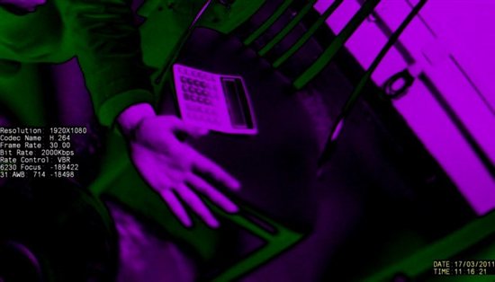
I use the Camera Interface(I/F) to receive video data, like below:
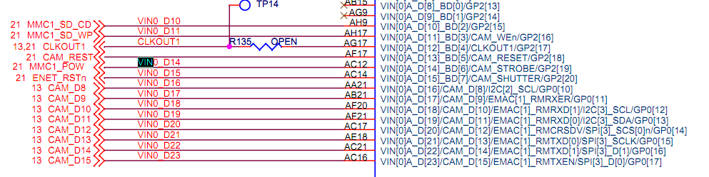
Can the interface(by 16bit data/clk/vsync/hsync) accept the embeded or discrete sync BT.1120 data?
If yes, could give me any direction to do it. Thanks.
Best Regards,
Xue
Hi ,
I use the Camera Interface(I/F) to receive video data, like below:
Can the interface(by 16bit data/clk/vsync/hsync) accept the embeded or discrete sync BT.1120 data?
If yes, could give me any direction to do it. Thanks.
Best Regards,
Xue