A related question is a question created from another question. When the related question is created, it will be automatically linked to the original question.
If you have a related question, please click the "Ask a related question" button in the top right corner. The newly created question will be automatically linked to this question.
i want to put a sinus signal to the audio in port of the OMAP-L138 and show the wave in CCS. If anyone has got any tips i would appreciate it when anyone tells me.
Although the best forum to ask device-related questions would be the OMAPL1, I strongly suggest you to take a look at the excellent hands-on workshops available at the link below:
These workshops contain all necessary material that guides you through the creation of a project, the use of our RTOS (SYSBIOS) and the interaction with hardware.
Please explore the modules under C6000™ High Performance DSP and SYS/BIOS™ Training as they use OMAPL138 boards as their hardware platform.
Example 2.7 on page 62 of "Digital Signal Processing and Applications with the OMAP - L138 eXperimenter" does precisely what you are asking for. You don't say exactly what hardware you're using but this book is accompanied by program files for the OMAP-L138 eXperimenter, the OMAP-L138 LCDK, and the C6748 LCDK
@donald: the book you describe would possibly be exactly what i am looking for, but i am a student and i cant really afford it.. maybe i can find solution other way
I have now tried the example 2.7 from your book and everything works fine but i have one question. Which amplitude did you choose for audio in?
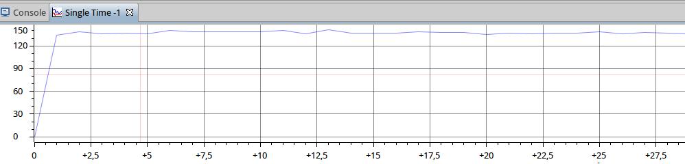
In the datasheet from the AIC3106 codec is a value of typical 0.7 Vrms. For security reasons i have tried 0.035 Vrms and the wave does not look like a sinus.
You say that everything is working fine but then contradict this by saying that the wave (the data stored in inbuffer, I presume) does not look like a sinus.
I have just reproduced the result shown on page 62 of the book and to get sample values in the range +/-9000 the input signal is 1V peak to peak.
The 35mV rms you say you are using is quite small. However, I just tried the program with a smaller input amplitude and got the results attached .
Channel 1 on the 'scope is the output (filtered using a first order CR filter to get rid of out-of-band noise, as per page 68 of the book) and channel 2 is the input.
As you can see the samples processed by the program are in the range +/-500.
Glad to hear you've got the program working. You shouldn't need to add anything to the code in order to view the contents of inbuffer. If you halt the program that is listed in the book, inbuffer should contain the BUFSIZE most recent input samples read from the ADC.


