This thread has been locked.

If you have a related question, please click the "Ask a related question" button in the top right corner. The newly created question will be automatically linked to this question.

OMAP-L138 Apparent back-feed from 1.8V rail to 3.3V rail

Other Parts Discussed in Thread: OMAP-L138

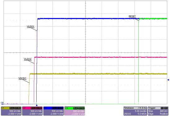
Questions of observation of apparent back-feed from 1.8V rail to 3.3V rail. Background: We power on 2 of the 3 the OMAP rails (+1.2V and +1.8V ) first, shortly after power up. Then we wait 200ms for all other processes to complete before turning on a FET to allow the 3.3V rail to turn on. All the OMAP I/O supplies are run from this 3.3V rail. We see on a scope that the +3V3 rail is being pulled up by a pretty stiff source to about 1.8V for about 60mS, after the 1.8V is already powered up (we tried loading it with additional 100mA and the characteristics of the 3V3 startup barely changed). After the 60mS the 3.3V ramps up to its final 3.3V level and stays there, so all 3 rails end up OK. So I am trying to understand why there is a two step bump in our +3V3 rail while the rail is shut off. We do have a +2V5 rail on the board, but it does not physically connect or share anything with the +3V3 except at one FPGA. We observe this behavior even when the FPGA is unprogrammed. Since the +1V8 is solely there to power up the OMAP (and we don't use DDR memory, so it doesn't do much except that the datasheet says it has to be there) and the Errata sheet draws the power sequencing as a small curve, I expected the first curve in all the other three boards, but this one board is the only one that shows the two bump behavior before +3V3 startup behavior. Any help on explanation would be greatly appreciated. Our concern is for some FPGAs on the board, which have ramp timing requirements. This step behavior may be an issue for them, so we are trying to both understand its cause, and determine if it is an issue.]

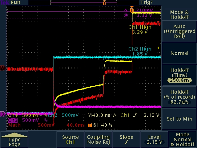
1.8V rail is blue, 3.3V rail is yellow.


  • John Wiemeyer said:

    Then we wait 200ms for all other processes to complete before turning on a FET to allow the 3.3V rail to turn on. All the OMAP I/O supplies are run from this 3.3V rail.

    What ‘processes’ are you waiting to complete? Here is an image from an application note on how to power sequence the OMAP-L138:

    The vertical time divisions are 5 ms. So, in this app note the 1.2V rail is powered on, then the 1.8V rail, and then the 3.3V rail is powered on all within 5 ms.

    The power leakage is a known issue between the 1.8V rail and the 3.3V rail that you seem to be aware of. That is why you expected the first bump in your graph. What the errata does not state and what your issue seems to prove is that if the leakage is allowed to occur for a long enough amount of time (200ms) before the 3.3V rail is turned on then it will get to a point where the detection circuitry of the 3.3V rail will assume that it is going to be powered from 1.8V (since this 3.3V rail is actually a dual supply rail named DVDD3318 that can be powered by either 1.8V or 3.3V which is a decision made by the detection circuitry during reset).

    Nowhere in the power sequence app notes nor the errata sheet is a delay between powering up the 3 rails mentioned as necessary. If you are adding the delay for the benefit of the OMAP-L138 then this delay should be removed. If you must have a 200 ms delay after powering on the 1.2V rail then I would suggest waiting until after the delay to power on the 1.8V rail and then a very short time after powering the 3.3V rail. You do not seem to need the 1.8V rail elsewhere on their board judging by this statement:

    John Wiemeyer said:

    Since the +1V8 is solely there to power up the OMAP (and we don't use DDR memory, so it doesn't do much except that the datasheet says it has to be there)

    So, I would suggest trying this power up sequence if you must have the delay for other components on your board:

                    Power the 1.2V rail -> delay for 200 ms -> power the 1.8V rail -> power the 3.3V rail

    Thanks,

    Jason Reeder