This thread has been locked.

If you have a related question, please click the "Ask a related question" button in the top right corner. The newly created question will be automatically linked to this question.

OMAP3530: Internal Pull-up / Pull-down maximum strength

Other Parts Discussed in Thread: OMAP3530

Measurements indicate that the OMAP3530 internal Pull-Down (PD) strength is far from the TI stated values in Datasheet rev F.

What is the maximum PU/PD strength to be taken into account for OMAP CBB package, please?

This is required for designing, with correct margins, external PU / PD with opposite pull at start with OMAP3530 device variations.


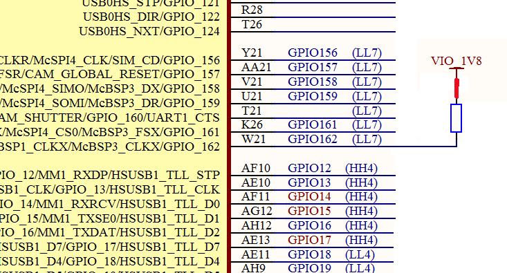
Measurements on GPIO162 (pin W21) is LL7. - Should have 100 uA PU/PD:

Measured PD = 3.85k (0.5V) with a PU = 10K and PD = 4.3K (0.86V) with a PU = 4K7.

This gives a PD strength of 467 uA - almost 5 times greater than 100 uA.


OMAP GPIO PU/PD strengths are defined as 100 uA or 1mA on some designated pins - which is equivalent to 18K and 1K8.

Datasheet SPRS507F (Rev F):

"The pull-up/pull-down drive strength is equal to 100 uA except for CBB balls P27, P26, R27, and R25 and CUS balls N22, N21, N20, and P24, which the pull- down drive strength is equal to 1.8 K."


On some pins Note (4): "The PU nominal drive strength of this IO cell is equal to 25 uA @ 1.8 V and 41.6 uA @ 3.0 V. The PD nominal drive strength of this IO cell is equal to 1 mA @ 1.8 V and 1.66 mA @ 3.0 V."

  • Hi Francois,

    Could you provide more information about configuration of the measured pin? It should be set as RX disabled.

    Could you explain more detailed and attach a picture of the schematic and measuring environment to clarify what exactly doing. 

    BR

    Tsvetolin Shulev

  • Hello Cvetolin,


    The OMAP3530 GPIO162 pin W21 (package CBB) is connected to an external pull-up (PU)  resistor connected to 1V8 OMAP vdds power domain - see image attached.

    We did set-up this test in order to have no other effect than the external PU on the pin (same power domain, no extra load).

    The GPIO162 is configured as Output - therefore the internal PD is opposite the external P only before the pad is set to Output.

    For the transient time between the OMAP power-on state and the GPIO162 set as output - the internal PD oppose the external PU connected.

    We recorded the voltage at the GPIO162 with an oscilloscope - it is 0.5V with ext. PU 10K and 0.86V with ext. PU 4K7.

    I hope this helps clarify the test.

    Best regards


    Francois Arnaud

  • Hi Francois,

    I only wish to add that the measurement would be start when the booting process is completed to be sure that the configuration of the ports is applied.

    BR

    Tsvetolin Shulev

  • Hi Tsvetolin,


    We are interested by the logic level of GPIO configured as Output during the Power-ON to GPIO output being active.

    This is required for having the correct logic level at start and not a toggle during few 100ms.

    You will find attached an oscilloscope snpshot of this transient time.

    The time of interest is where the voltage is 0.86 V, afterwards the output is active and the level immediately at 1V8 power domain.

    I hope this helps.


    Best regards,


    Francois Arnaud


  • Hi Francois,

    The value of the OMAP GPIO PU/PD strengths described in the datasheet refers to the time after bootimg and initialization. It is not clear what strengths would be before this moment.


    BR

    Tsvetolin Shulev

  • Hello Tsvetolin,


    I do not agree with your statement "It is not clear what strengths would be before this moment.".

    According to TI OMAP3530  datasheet rev F page 27 we have Ball Reset State [6] at reset - (power-up) defined:

     "BALL RESET STATE:

    The state of the terminal at reset (power up).

    – 0: The buffer drives VOL (pulldown/pullup resistor not activated)

        0(PD): The buffer drives VOL with an active pulldown resistor.

    – 1: The buffer drives VOH (pulldown/pullup resistor not activated)

         1(PU): The buffer drives VOH with an active pullup resistor.

    – Z: High-impedance

    – L: High-impedance with an active pulldown resistor

    – H : High-impedance with an active pullup resistor


    This section [6] indicates indeed what PU/PD strengths we should expect from power-up.

    Section [7] 'BALL RESET REL. STATE' give us the PU/PD strengths at reset release.


    Best regards,


    Francois Arnaud