Hi,
I have two questions regarding the power up condition of OMAP-L138.
1) According to the "Table 12. Bulk Capacitance" in Advisory 2.1.18 of the errata sheet, it is written DCDD3318_x ramp time for 3.3V. The longest time is 10ms in the table.
Does this mean that OMAP-L138 can allow ramp tim for 3.3V until maximum 10ms. And is the longer time than 10ms out of spec for OMAP-L138? Is there any spec for maximum power-up time?
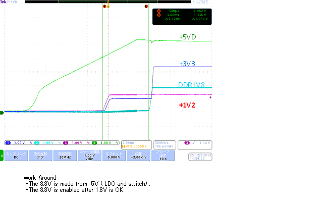
2) During the DVDD18 is ramping up, DVDD3318(3.3V ) supply is cut off at the moment by external circuit. At this time, DVDD18 increase to near 2.7V at the moment.
The above is one experiment. is this codition allowed for OMAP-L138?
Please advise me.
Best regards,
Michi