hi all,
Test is well below the source to the DSP within.
/****************************************************************************\
 *           Copyright (C) 2009 Texas Instruments Incorporated.             *
 *
 *  Redistribution and use in source and binary forms, with or without
 *  modification, are permitted provided that the following conditions
 *  are met:
 *
 *    Redistributions of source code must retain the above copyright
 *    notice, this list of conditions and the following disclaimer.
 *
 *    Redistributions in binary form must reproduce the above copyright
 *    notice, this list of conditions and the following disclaimer in the
 *    documentation and/or other materials provided with the
 *    distribution.
 *
 *    Neither the name of Texas Instruments Incorporated nor the names of
 *    its contributors may be used to endorse or promote products derived
 *    from this software without specific prior written permission.
 *
 *  THIS SOFTWARE IS PROVIDED BY THE COPYRIGHT HOLDERS AND CONTRIBUTORS
 *  "AS IS" AND ANY EXPRESS OR IMPLIED WARRANTIES, INCLUDING, BUT NOT
 *  LIMITED TO, THE IMPLIED WARRANTIES OF MERCHANTABILITY AND FITNESS FOR
 *  A PARTICULAR PURPOSE ARE DISCLAIMED. IN NO EVENT SHALL THE COPYRIGHT
 *  OWNER OR CONTRIBUTORS BE LIABLE FOR ANY DIRECT, INDIRECT, INCIDENTAL,
 *  SPECIAL, EXEMPLARY, OR CONSEQUENTIAL DAMAGES (INCLUDING, BUT NOT
 *  LIMITED TO, PROCUREMENT OF SUBSTITUTE GOODS OR SERVICES; LOSS OF USE,
 *  DATA, OR PROFITS; OR BUSINESS INTERRUPTION) HOWEVER CAUSED AND ON ANY
 *  THEORY OF LIABILITY, WHETHER IN CONTRACT, STRICT LIABILITY, OR TORT
 *  (INCLUDING NEGLIGENCE OR OTHERWISE) ARISING IN ANY WAY OUT OF THE USE
 *  OF THIS SOFTWARE, EVEN IF ADVISED OF THE POSSIBILITY OF SUCH DAMAGE.
 *
*/
#include <stdio.h>
#include <stdlib.h>
#include <string.h>
#include <c6x.h>
#include <ti/csl/src/intc/csl_intc.h>

#include <sfp\BSLC667X_sfp.h>
#include <ti\csl\csl_pscAux.h>
#include <control/BSLC667X_control.h>

#include "..\src\Aif2_config.h"

#define DEBUG_NON_RP1_TIMING	1

//Users should use 16 bytes aligned(Quad word) data for Aif2 and PktDMA data flow
#pragma DATA_ALIGN (dio_data, 16)
Uint32              dio_data[16 * 4 * 32];
#pragma DATA_ALIGN (dio_result, 16)
Uint32              dio_result[16 * 4 * 32];

/* Intc variable declarartion */
CSL_IntcObj    intcObj;
CSL_IntcHandle   hIntc;
CSL_IntcEventHandlerRecord  EventHandler[8];
CSL_IntcGlobalEnableState state;

/* Global structures and variables  */
CSL_Aif2Obj Aif2Obj;// Aif2 CSL object
CSL_Aif2Handle hAif2;// Aif2 handle
Bool ctrlArg; // Ctrl Argument;

CSL_Aif2Context Aif2Context;//Aif2 context
CSL_Aif2Param  aif2Param;//AIF2 module specific parameters
CSL_Status status; // CSL status

CSL_Aif2Setup               aif2Setup;//Aif2 HW setup
CSL_Aif2LinkSetup           linkSetup;// Setup for links
CSL_Aif2GlobalSetup         globalSetup;// global config for AIF2
CSL_Aif2CommonSetup         commonSetup; // Setup for common params

CSL_Aif2SdCommonSetup       SdCommonSetup;//SERDES common setup
CSL_Aif2PdCommonSetup       PdCommonSetup;//PD common setup
CSL_Aif2PeCommonSetup       PeCommonSetup;//PE common setup
CSL_Aif2IngrDbSetup         IngrDbSetup;// Ingress data buffer setup
CSL_Aif2EgrDbSetup          EgrDbSetup;// Egress data buffer setup
CSL_Aif2AdCommonSetup       AdCommonSetup;// Aif2 DMA common setup
CSL_Aif2AdDioSetup          AdDioSetup;// Aif2 DIO common setup
CSL_Aif2AtCommonSetup       AtCommonSetup; // Aif2 Timer common  setup
CSL_Aif2AtEventSetup        AtEventSetup; // Aif2 Timer external and internal event  setup
CSL_Aif2AtCountObj          PhyTimerTc;// AT Phy Terminal Count setup
CSL_Aif2AtCountObj          RadTimerTc;// AT Rad Terminal Count setup
CSL_Aif2AtCountObj          PhyTimerInit;// AT Phy Init value setup
CSL_Aif2AtCountObj          RadTimerInit;// AT Rad Init value setup
CSL_Aif2AtCountObj          UlRadTimerInit;// AT Rad Init value setup

CSL_Aif2CommonLinkSetup     ComLinkSetup; // Aif2 link common setup
CSL_Aif2SdLinkSetup         SdLinkSetup; //SERDES link setup
CSL_Aif2RmLinkSetup         RmLinkSetup; //RM link setup
CSL_Aif2TmLinkSetup         TmLinkSetup; //TM link setup
CSL_Aif2PdLinkSetup         PdLinkSetup; //PD link setup
CSL_Aif2PeLinkSetup         PeLinkSetup; //PE link setup
CSL_Aif2RtLinkSetup         RtLinkSetup; //RT link setup
CSL_Aif2AtLinkSetup         AtLinkSetup; // Aif2 timer link setup (Pi, Delta, PE signal)

volatile unsigned int int4_result;

interrupt void int4_isr(){

   int4_result++;
}

void Intc_config(void)
{
   CSL_IntcParam    vectId;
   CSL_IntcContext  context;
   //!!!!!!!!!!!!!!!!!!!!!!!!!!!!!!!!!!!!!!!!//
   //! GEM0 Intc Configuration              !//
   //!!!!!!!!!!!!!!!!!!!!!!!!!!!!!!!!!!!!!!!!//
   /* Setup the global Interrupt */
   context.numEvtEntries = 8;
   context.eventhandlerRecord = EventHandler;
   CSL_intcInit(&context);
   /* Enable NMIs  */
   CSL_intcGlobalNmiEnable();
   /* Enable Global Interrupts  */
   CSL_intcGlobalEnable(&state);

   /* VectorID for the Global Edma Event  */
   vectId = CSL_INTC_VECTID_4;

   /* Opening a handle for the Fsync->EDMA Interrupt Event */
   hIntc   = CSL_intcOpen(&intcObj,
                           AIF2_EVENT7_INTSEL_MAP, // Event7
                           &vectId,
                           NULL);
   //Hook the ISRs
   CSL_intcHookIsr(vectId,  &int4_isr);
   // Clear the Interrupt
   CSL_intcHwControl(hIntc, CSL_INTC_CMD_EVTCLEAR,  NULL);
   //Enable the Event & the interrupt
   CSL_intcHwControl(hIntc, CSL_INTC_CMD_EVTENABLE,  NULL);
}


void Aif2_Dio_Cpri_Tac_config(CSL_Aif2LinkIndex link)
{
   BSLC667X_ErrorCode Err;
   unsigned short usRegVal;
   int i;

   //////////////////Initialize Aif2 structures to avoid unwanted configuration ////////////////////////////////////////
   memset(&globalSetup, 0, sizeof(globalSetup));
   memset(&linkSetup, 0, sizeof(linkSetup));
   memset(&commonSetup, 0, sizeof(commonSetup));

   memset(&SdCommonSetup, 0, sizeof(SdCommonSetup));
   memset(&PdCommonSetup, 0, sizeof(PdCommonSetup));
   memset(&PeCommonSetup, 0, sizeof(PeCommonSetup));
   memset(&IngrDbSetup, 0, sizeof(IngrDbSetup));
   memset(&EgrDbSetup, 0, sizeof(EgrDbSetup));
   memset(&AdCommonSetup, 0, sizeof(AdCommonSetup));
   memset(&AdDioSetup, 0, sizeof(AdDioSetup));
   memset(&AtCommonSetup, 0, sizeof(AtCommonSetup));
   memset(&AtEventSetup, 0, sizeof(AtEventSetup));
   memset(&PhyTimerInit, 0, sizeof(PhyTimerInit));
   memset(&RadTimerInit, 0, sizeof(RadTimerInit));
   memset(&UlRadTimerInit, 0, sizeof(UlRadTimerInit));
   memset(&PhyTimerTc, 0, sizeof(PhyTimerTc));
   memset(&RadTimerTc, 0, sizeof(RadTimerTc));

   memset(&ComLinkSetup, 0, sizeof(ComLinkSetup));
   memset(&SdLinkSetup, 0, sizeof(SdLinkSetup));
   memset(&RmLinkSetup, 0, sizeof(RmLinkSetup));
   memset(&TmLinkSetup, 0, sizeof(TmLinkSetup));
   memset(&PdLinkSetup, 0, sizeof(PdLinkSetup));
   memset(&PeLinkSetup, 0, sizeof(PeLinkSetup));
   memset(&RtLinkSetup, 0, sizeof(RtLinkSetup));
   memset(&AtLinkSetup, 0, sizeof(AtLinkSetup));

   // Initialize CSL library, this step is required
   CSL_aif2Init(&Aif2Context);

   // Open Aif2 and get handle
   hAif2 = CSL_aif2Open(&Aif2Obj, CSL_AIF, &aif2Param, &status);

   if ((hAif2 == NULL) || (status != CSL_SOK))
   {
      printf ("\nError opening CSL_AIF2");
      exit(1);
   }

   /////////////////populating AIF2 major setup structures //////////////////////////////////////////////////////////
   aif2Setup.globalSetup = &globalSetup;
   aif2Setup.commonSetup = &commonSetup;
   aif2Setup.linkSetup[link] = &linkSetup;//assign only one link setup for link 0

   // populate global config fields
   globalSetup.ActiveLink[link] = TRUE;//Activate link 0 for this test
   globalSetup.frameMode = CSL_AIF2_FRAME_MODE_NORMAL;

   //populate common config fields
   commonSetup.pSdCommonSetup = &SdCommonSetup;
   commonSetup.pPdCommonSetup = &PdCommonSetup;
   commonSetup.pPeCommonSetup = &PeCommonSetup;
   commonSetup.pIngrDbSetup   = &IngrDbSetup;
   commonSetup.pEgrDbSetup    = &EgrDbSetup;
   commonSetup.pAdCommonSetup = &AdCommonSetup;
   commonSetup.pAdDioSetup    = &AdDioSetup;
   commonSetup.pAtCommonSetup = &AtCommonSetup;
   commonSetup.pAtEventSetup  = &AtEventSetup;

   ////////////Link Setup (Do this setup repeatedly with different link setup structure if user wants to use multiple links)////////////
   //populate link config fields for link 0
   linkSetup.linkIndex     = link;
   linkSetup.pComLinkSetup = &ComLinkSetup;
   linkSetup.pSdLinkSetup  = &SdLinkSetup;
   linkSetup.pRmLinkSetup  = &RmLinkSetup;
   linkSetup.pTmLinkSetup  = &TmLinkSetup;
   linkSetup.pPdLinkSetup  = &PdLinkSetup;
   linkSetup.pPeLinkSetup  = &PeLinkSetup;
   linkSetup.pRtLinkSetup  = &RtLinkSetup;
   linkSetup.pAtLinkSetup  = &AtLinkSetup;

   //Link Common setup
   ComLinkSetup.linkProtocol = CSL_AIF2_LINK_PROTOCOL_CPRI;
   ComLinkSetup.linkRate = CSL_AIF2_LINK_RATE_4x;
   ComLinkSetup.IngrDataWidth = CSL_AIF2_DATA_WIDTH_15_BIT;
   ComLinkSetup.EgrDataWidth = CSL_AIF2_DATA_WIDTH_15_BIT;

   //SD link setup
   SdLinkSetup.rxAlign = CSL_AIF2_SD_RX_COMMA_ALIGNMENT_ENABLE;
   SdLinkSetup.rxLos = CSL_AIF2_SD_RX_LOS_ENABLE;
   SdLinkSetup.rxCdrAlgorithm = CSL_AIF2_SD_RX_CDR_FIRST_ORDER_THRESH_17;
   SdLinkSetup.rxInvertPolarity = CSL_AIF2_SD_RX_NORMAL_POLARITY;
   SdLinkSetup.rxTermination = CSL_AIF2_SD_RX_TERM_COMMON_POINT_0_7 ;//for AC coupled application
   SdLinkSetup.rxEqualizerConfig = CSL_AIF2_SD_RX_EQ_ADAPTIVE;//Equalizer On
   SdLinkSetup.bRxEqHold = FALSE;//fixed value
   SdLinkSetup.bRxOffsetComp = TRUE;//fixed value
   SdLinkSetup.bEnableTxSyncMater = TRUE; //fixed value
   SdLinkSetup.txInvertPolarity = CSL_AIF2_SD_TX_PAIR_NORMAL_POLARITY;
   SdLinkSetup.txOutputSwing = CSL_AIF2_SD_TX_OUTPUT_SWING_14;
   SdLinkSetup.txPrecursorTapWeight = CSL_AIF2_SD_TX_PRE_TAP_WEIGHT_2;// -5%
   SdLinkSetup.txPostcursorTapWeight = CSL_AIF2_SD_TX_POST_TAP_WEIGHT_24;// -20%
   SdLinkSetup.bTxFirFilterUpdate = TRUE;//FIR filter update on

   //TM link setup
   TmLinkSetup.bEnableTmLink = TRUE;
   TmLinkSetup.bEnableRmLos = FALSE;
   TmLinkSetup.SeedValue = 0x1;
   TmLinkSetup.bEnableScrambler = FALSE;
   TmLinkSetup.pCpriTmSetup.L1InbandEn = 0;//disable 9 bits mask
   TmLinkSetup.pCpriTmSetup.RmLinkLosError = link;//select link 0 as source RM link
   TmLinkSetup.pCpriTmSetup.RmLinkLofError = link;//select link 0 as source RM link
   TmLinkSetup.pCpriTmSetup.RmLinkLosRx = link;//select link 0 as source RM link
   TmLinkSetup.pCpriTmSetup.RmLinkLofRx = link;//select link 0 as source RM link
   TmLinkSetup.pCpriTmSetup.RmLinkRaiRx = link;//select link 0 as source RM link
   TmLinkSetup.pCpriTmSetup.TxStartup = 0;
   TmLinkSetup.pCpriTmSetup.TxPointerP = 20;//for Ethernet channel
   TmLinkSetup.pCpriTmSetup.TxProtocolVer = 1;

   //RM link setup
   RmLinkSetup.bEnableRmLink = TRUE;
   RmLinkSetup.RmFifoThold = CSL_AIF2_RM_FIFO_THOLD_IMMEDIATELY;
   RmLinkSetup.RmErrorSuppress = CSL_AIF2_RM_ERROR_ALLOW;
   RmLinkSetup.bEnableSdAutoAlign = FALSE;
   RmLinkSetup.bEnableScrambler = FALSE;
   RmLinkSetup.bEnableLcvUnsync = FALSE;
   RmLinkSetup.bEnableLcvControl = FALSE;
   RmLinkSetup.bEnableWatchDog = FALSE;
   RmLinkSetup.WatchDogWrap = 0xFF;//set watch dog wrap value
   RmLinkSetup.bEnableClockQuality = FALSE;
   RmLinkSetup.ClockMonitorWrap = 0;
   RmLinkSetup.losDetThreshold = RM_LOS_DET_THOLD;
   RmLinkSetup.SyncThreshold = RM_SYNC_THOLD;
   RmLinkSetup.FrameSyncThreshold = RM_SYNC_THOLD;
   RmLinkSetup.UnsyncThreshold = RM_UNSYNC_THOLD;
   RmLinkSetup.FrameUnsyncThreshold = RM_UNSYNC_THOLD;

   //RT link setup
   RtLinkSetup.CiSelect =  link;
   RtLinkSetup.bEnableEmptyMsg = TRUE;
   RtLinkSetup.RtConfig = CSL_AIF2_RT_MODE_TRANSMIT;// takes PE input only

   //PD link setup
   PdLinkSetup.bEnablePdLink = TRUE;
   PdLinkSetup.CpriEnetStrip = 1;//enable ethernet strip for control channel 0
   PdLinkSetup.Crc8Poly = CRC8_POLY;
   PdLinkSetup.Crc8Seed = CRC8_SEED;
   PdLinkSetup.CpriCwNullDelimitor = 0xFB;//K 27.7 charactor
   PdLinkSetup.CpriCwPktDelimitor[0] = CSL_AIF2_CW_DELIM_NULLDELM;//4
   PdLinkSetup.PdCpriCrcType[0] = CSL_AIF2_CRC_16BIT;
   PdLinkSetup.bEnableCpriCrc[0] = FALSE;//enable CPRI CRC for control channel 0
   PdLinkSetup.PdPackDmaCh[0] = 124;//Set DB channel 124 as a dma ch for control channel 0
   PdLinkSetup.bEnablePack[0] = FALSE;//enable CPRI control channel 0 packing

   PdLinkSetup.PdCpriDualBitMap.DbmX = 15;// for 4x link speed with 15 bit data. set X-1
   PdLinkSetup.PdCpriDualBitMap.DbmXBubble = 1;//2 bubbles of 1 AxC sample
   PdLinkSetup.PdCpriDualBitMap.Dbm1Mult = 0;//set n-1
   PdLinkSetup.PdCpriDualBitMap.Dbm1Size = 0;//set n-1
   PdLinkSetup.PdCpriDualBitMap.Dbm1Map[0] = 0x0;
   PdLinkSetup.PdCpriDualBitMap.Dbm2Size = 0;
   PdLinkSetup.PdCpriDualBitMap.Dbm2Map[0] = 0x0;
   for(i=0;i<16;i++)//cpri id lut setup for X position 0 ~ 15
   {
   PdLinkSetup.CpriDmaCh[i]= i; //DbmX channel num (X position num and DB channel number is same in this test)
   PdLinkSetup.bEnableCpriX[i]= TRUE; //enable CPRI X channel
   PdLinkSetup.bEnableCpriPkt[i]= FALSE;//use AxC data mode
   PdLinkSetup.Cpri8WordOffset[i]= 0;//word level CPRI data offset (fine AxC offset)
   }
    for(i=0;i<256;i++)//cpri cw lut setup
   {
   PdLinkSetup.CpriCwChannel[i]= 0; //set cw channel num to pack 0
   PdLinkSetup.bEnableCpriCw[i]= FALSE; //disable CW sub channel
   }

   //PE link setup
   PeLinkSetup.bEnablePeLink = TRUE;
   PeLinkSetup.PeCppiDioSel = CSL_AIF2_DIO;
   PeLinkSetup.Crc8Poly = CRC8_POLY;
   PeLinkSetup.Crc8Seed = CRC8_SEED;
   PeLinkSetup.PeDelay = DB_PE_DELAY_CPRI;
   PeLinkSetup.PeCpriDualBitMap.DbmX = 15;// for 4x link speed with 15 bit data. set X-1
   PeLinkSetup.PeCpriDualBitMap.DbmXBubble = 1;//2 bubbles of 1 AxC sample
   PeLinkSetup.PeCpriDualBitMap.Dbm1Mult = 0;//set n-1
   PeLinkSetup.PeCpriDualBitMap.Dbm1Size = 0;//set n-1
   PeLinkSetup.PeCpriDualBitMap.Dbm1Map[0] = 0x0;
   PeLinkSetup.PeCpriDualBitMap.Dbm2Size = 0;
   PeLinkSetup.PeCpriDualBitMap.Dbm2Map[0] = 0x0;
   PeLinkSetup.CpriAxCPack = CSL_AIF2_CPRI_15BIT_SAMPLE;
   PeLinkSetup.CpriCwNullDelimitor = 0xFB;//K 27.7 charactor
   PeLinkSetup.CpriCwPktDelimitor[0] = CSL_AIF2_CW_DELIM_NULLDELM;
   PeLinkSetup.PePackDmaCh[0] = 124;
   PeLinkSetup.bEnablePack[0] = FALSE;
    for(i=0;i<256;i++)//cpri cw lut setup
   {
    PeLinkSetup.CpriCwChannel[i]= 0; //set cw channel num to pack 0
    PeLinkSetup.bEnableCpriCw[i]= FALSE; //disable CPRI CW
   }

   //AT link setup
   AtLinkSetup.PE1Offset = 470;
   AtLinkSetup.PE2Offset = 490;
   AtLinkSetup.DeltaOffset = 560;//TAC delay(230) + CPRI Egress 4 chip DMA delay(240) + 90
   AtLinkSetup.PiMin = 560;
   AtLinkSetup.PiMax = 580;
   AtLinkSetup.IsNegativeDelta = FALSE;//positive delta

   //////////////////// Common Setup  ///////////////////////////////////////////////////////
   //SD common setup
   SdCommonSetup.bEnablePllB8 = TRUE;
   SdCommonSetup.CLKBYP_B8 = CSL_AIF2_PLL_CLOCK_NO_BYPASS;
   SdCommonSetup.LB_B8 = CSL_AIF2_PLL_LOOP_BAND_MID;//High BW is also fine
   SdCommonSetup.VoltRangeB8 = CSL_AIF2_PLL_VOLTAGE_LOW;//fixed factor
   SdCommonSetup.SleepPllB8 = CSL_AIF2_PLL_AWAKE;
   SdCommonSetup.pllMpyFactorB8 = CSL_AIF2_PLL_MUL_FACTOR_20X;//for CPRI when reference clock is 122.88 Mhz
   SdCommonSetup.SysClockSelect = CSL_AIF2_SD_BYTECLOCK_FROM_B8;
   SdCommonSetup.DisableLinkClock[0] = FALSE;//enable LINK0 clock
   SdCommonSetup.DisableLinkClock[1] = FALSE;//enable LINK1 clock
   SdCommonSetup.DisableLinkClock[2] = FALSE;//enable LINK2 clock
   SdCommonSetup.DisableLinkClock[3] = TRUE;//disable LINK3 clock
   SdCommonSetup.DisableLinkClock[4] = TRUE;//disable LINK4 clock
   SdCommonSetup.DisableLinkClock[5] = TRUE;//disable LINK5 clock

   //PD common setup
   PdCommonSetup.PdCppiDioSel = CSL_AIF2_DIO;//DIO
   PdCommonSetup.AxCOffsetWin = AXC_OFFSET_WIN;//only used for OBSAI
   PdCommonSetup.PdRadtTC = 2457599;// Radio frame size for CPRI
   PdCommonSetup.PdFrameTC[0].FrameIndexSc = 0;//start index
   PdCommonSetup.PdFrameTC[0].FrameIndexTc = 0;//teminal index
   PdCommonSetup.PdFrameTC[0].FrameSymbolTc = 14;//15 slots for WCDMA
   for(i=0;i<16;i++)//for channel 0 ~ 15
   {
   PdCommonSetup.PdChConfig[i].bChannelEn = TRUE;//Channel enable
   PdCommonSetup.PdChConfig[i].DataFormat = CSL_AIF2_LINK_DATA_TYPE_NORMAL;//Data format
   PdCommonSetup.AxCOffset[i] = 0;//Ingress AxC offset is not used for CPRI DIO
   PdCommonSetup.PdChConfig1[i].bTsWatchDogEn = FALSE;//disable watchdog
   PdCommonSetup.PdChConfig1[i].DataFormat = CSL_AIF2_GSM_DATA_OTHER;//Non GSM data
   PdCommonSetup.PdChConfig1[i].FrameCounter = 0;//framing counter group number
   PdCommonSetup.PdChConfig1[i].DioOffset = 0;//Use zero offset for simple test
   PdCommonSetup.PdChConfig1[i].TddEnable = 0xFFFF;//enables all symbols(FDD)
   PdCommonSetup.TddEnable1[i] = 0xFFFFFFFF;//enables all symbols(FDD)
   PdCommonSetup.TddEnable2[i] = 0xFFFFFFFF;//enables all symbols(FDD)
   PdCommonSetup.TddEnable3[i] = 0xFFFFFFFF;//enables all symbols(FDD)
   PdCommonSetup.TddEnable4[i] = 0xFFFFFFFF;//enables all symbols(FDD)
   }
   PdCommonSetup.PdFrameMsgTc[0] = 639; // 640 CPRI quad samples (16 byte) are in  WCDMA slot time

   //PE common setup
   PeCommonSetup.PeTokenPhase = 0;//Phase alignment for scheduling DMA. normally set to zero
   PeCommonSetup.EnetHeaderSelect = 1;//bit order for Ethernet preamble and SOF
   PeCommonSetup.GlobalDioLen = CSL_AIF2_DB_DIO_LEN_128;
   PeCommonSetup.PeFrameTC[0].FrameIndexSc = 0;//start index
   PeCommonSetup.PeFrameTC[0].FrameIndexTc = 0;//teminal index
   PeCommonSetup.PeFrameTC[0].FrameSymbolTc = 14;//Set 14 for WCDMA
   for(i=0;i<16;i++)//for channel 0 ~ 15
   {
   PeCommonSetup.bEnableCh[i] = TRUE;//Enable PE channel
   PeCommonSetup.PeDmaCh0[i].bCrcEn = FALSE;//disable CRC
   PeCommonSetup.PeDmaCh0[i].FrameTC = 0;//use framing terminal count 0
   PeCommonSetup.PeDmaCh0[i].RtControl = CSL_AIF2_PE_RT_INSERT;//use PE insert option
   PeCommonSetup.PeDmaCh0[i].CrcType = CSL_AIF2_CRC_8BIT;//CRC type
   PeCommonSetup.PeDmaCh0[i].isEthernet = FALSE;//AxC data
   PeCommonSetup.PeInFifo[i].SyncSymbol = 0;//Sync symbol offset
   PeCommonSetup.PeInFifo[i].MFifoWmark = 2;//Message FIFO water mark
   PeCommonSetup.PeInFifo[i].MFifoFullLevel = 3;//Message FIFO full level
   PeCommonSetup.PeAxcOffset[i] = 490;//same to PE2 offset when there's no external offset
   }
   PeCommonSetup.PeFrameMsgTc[0] = 2559;//2560 CPRI samples (4 byte) are in  WCDMA slot time

   //PE Channel LUT setup and link routing selection (ChIndex number is matched with link number)
  for (i=0; i<16; i++)
   {
		switch(link)
		{
		case CSL_AIF2_LINK_0:
		     PeCommonSetup.ChIndex0[i] = i; //channel 0 ~ 15
		     PeCommonSetup.bEnableChIndex0[i] = TRUE;//Route egress channel 0 ~ 15 dbm rule to modulo rule 0
		     PeCommonSetup.CpriPktEn0[i] = FALSE;
			break;
		case CSL_AIF2_LINK_1:
		     PeCommonSetup.ChIndex1[i] = i; //channel 0 ~ 15
		     PeCommonSetup.bEnableChIndex1[i] = TRUE;//Route egress channel 0 ~ 15 dbm rule to modulo rule 0
		     PeCommonSetup.CpriPktEn1[i] = FALSE;
			break;
		case CSL_AIF2_LINK_2:
		     PeCommonSetup.ChIndex2[i] = i; //channel 0 ~ 15
		     PeCommonSetup.bEnableChIndex2[i] = TRUE;//Route egress channel 0 ~ 15 dbm rule to modulo rule 0
		     PeCommonSetup.CpriPktEn2[i] = FALSE;
			break;
		default:
			printf("Link %d is not connected on this card\n", link);
		}
   }

   //Ingress DB setup
   IngrDbSetup.bEnableIngrDb = TRUE; //Enable Ingress DB
   IngrDbSetup.DioBufferLen = CSL_AIF2_DB_DIO_LEN_128; //Ingress DB DIO buffer length
   for (i=0; i<16; i++)
   {
     IngrDbSetup.bEnableChannel[i] = TRUE; //Enable 16 Ingress DB channel
     IngrDbSetup.IngrDbChannel[i].BaseAddress = (AIF2_DB_BASE_ADDR_I_FIFO_0 + i); //Set DB FIFO base address every 8 QW
     IngrDbSetup.IngrDbChannel[i].DataSwap = CSL_AIF2_DB_WORD_SWAP; //DL
     IngrDbSetup.IngrDbChannel[i].IQOrder = CSL_AIF2_DB_IQ_NO_SWAP; //No Order change
   }

   //Egress DB setup
   EgrDbSetup.bEnableEgrDb = TRUE; //Enable Egress DB
   EgrDbSetup.DioBufferLen = CSL_AIF2_DB_DIO_LEN_128; //Egress DB DIO buffer length
   EgrDbSetup.PmControl = CSL_AIF2_DB_PM_TOKEN_FIFO;//for normal packet performance
   for (i=0; i<16; i++)
   {
     EgrDbSetup.bEnableChannel[i] = TRUE; //Enable 16 Egress DB channel
     EgrDbSetup.EgrDbChannel[i].BaseAddress = (AIF2_DB_BASE_ADDR_E_FIFO_0 + i); //Set DB FIFO base address every 8 QW
     EgrDbSetup.EgrDbChannel[i].DataSwap = CSL_AIF2_DB_WORD_SWAP; //DL
     EgrDbSetup.EgrDbChannel[i].IQOrder = CSL_AIF2_DB_IQ_NO_SWAP; //No Order change
     EgrDbSetup.EgrDbChannel[i].EgressDioOffset = 0;//set zero for simple test
   }

   //AD Common and DIO setup
   AdCommonSetup.IngrGlobalEnable = TRUE;
   AdCommonSetup.EgrGlobalEnable = TRUE;
   AdCommonSetup.IngrGlobalDioEnable = TRUE;
   AdCommonSetup.EgrGlobalDioEnable = TRUE;
   AdCommonSetup.FailMode = CSL_AIF2_AD_DROP;//drop fail packet
   AdCommonSetup.IngrPriority = CSL_AIF2_AD_DIO_PRI;
   AdCommonSetup.EgrPriority = CSL_AIF2_AD_AXC_PRI;

   AdDioSetup.IngrDioEngineEnable[0] = TRUE;//Enable DIO Engine
   AdDioSetup.IngrDioEngine[0].BcnTableSelect = CSL_AIF2_AD_DIO_BCN_TABLE_0;
   AdDioSetup.IngrDioEngine[0].NumQuadWord = CSL_AIF2_AD_1QUAD;//Use 1 QW per channel
   AdDioSetup.IngrDioEngine[0].NumAxC = 15;//Use 16 AxC.
   AdDioSetup.IngrDioEngine[0].bEnDmaChannel = TRUE; //Enable Dma channel
   AdDioSetup.IngrDioEngine[0].DmaNumBlock = 31;//32 block wrap value (n-1)
   AdDioSetup.IngrDioEngine[0].DmaBurstLen = CSL_AIF2_AD_4QUAD;//4 max QW burst per one transfer
   AdDioSetup.IngrDioEngine[0].DmaBaseAddr = (Uint32)&dio_result[0];//DMA destination base address (use high 28 bits)
   AdDioSetup.IngrDioEngine[0].DmaBurstAddrStride = 4;//DMA burst stride to 4 (wrap1)
   AdDioSetup.IngrDioEngine[0].DmaBlockAddrStride = 16;//DMA block stride to 4 (wrap2)
   for (i=0; i<16; i++)
   AdDioSetup.IngrDioEngine[0].DBCN[i] = i; //set ingress table DBCN for 16 channels

   AdDioSetup.EgrDioEngineEnable[0] = TRUE;//Enable DIO Engine
   AdDioSetup.EgrDioEngine[0].BcnTableSelect = CSL_AIF2_AD_DIO_BCN_TABLE_0;
   AdDioSetup.EgrDioEngine[0].NumQuadWord = CSL_AIF2_AD_1QUAD;//Use 1 QW per channel
   AdDioSetup.EgrDioEngine[0].NumAxC = 15;//Use 16 AxC
   AdDioSetup.EgrDioEngine[0].bEnDmaChannel = TRUE; //Enable Dma channel
   AdDioSetup.EgrDioEngine[0].bEnEgressRsaFormat = FALSE;
   AdDioSetup.EgrDioEngine[0].DmaNumBlock = 31;//31 block wrap value (n-1)
   AdDioSetup.EgrDioEngine[0].DmaBurstLen = CSL_AIF2_AD_4QUAD;//4 max QW burst per one transfer
   AdDioSetup.EgrDioEngine[0].DmaBaseAddr = (Uint32)&dio_data[0];//DMA source base address (use high 28 bits)
   AdDioSetup.EgrDioEngine[0].DmaBurstAddrStride = 4;//DMA burst stride to 4 (wrap1)
   AdDioSetup.EgrDioEngine[0].DmaBlockAddrStride = 16;//DMA block stride to 4 (wrap2)
   for (i=0; i<16; i++)
   AdDioSetup.EgrDioEngine[0].DBCN[i] = i; //set egress table DBCN for 16 channels

#if DEBUG_NON_RP1_TIMING
   AtCommonSetup.PhySyncSel = CSL_AIF2_SW_SYNC;;//Select chip input sync for Phy timer trigger
   AtCommonSetup.RadSyncSel = CSL_AIF2_SW_SYNC;;//Select chip input sync for Rad timer trigger
#else
   AtCommonSetup.PhySyncSel = CSL_AIF2_CHIP_INPUT_SYNC;//CSL_AIF2_SW_SYNC;//Select chip input sync for Phy timer trigger
   AtCommonSetup.RadSyncSel = CSL_AIF2_CHIP_INPUT_SYNC;//CSL_AIF2_SW_SYNC;//Select chip input sync for Rad timer trigger
#endif
   AtCommonSetup.SyncMode = CSL_AIF2_NON_RP1_MODE;
   AtCommonSetup.AutoResyncMode = CSL_AIF2_AUTO_RESYNC_MODE;
   AtCommonSetup.CrcMode = CSL_AIF2_AT_CRC_DONT_USE;//Do not use RP1 CRC in this test

   AtCommonSetup.AtInit.pPhyTimerInit = &PhyTimerInit;
   AtCommonSetup.AtInit.pRadTimerInit = &RadTimerInit;
   AtCommonSetup.AtInit.pUlRadTimerInit = &UlRadTimerInit;
   AtCommonSetup.WcdmaDivTC = 63; //64 is default divide value for WCDMA CPRI
   PhyTimerInit.ClockNum = 0;
   PhyTimerInit.FrameLsbNum = 0;
   PhyTimerInit.FrameMsbNum = 0;
   RadTimerInit.ClockNum = 0;
   RadTimerInit.SymbolNum = 0;
   RadTimerInit.FrameLsbNum = 0;
   RadTimerInit.FrameMsbNum = 0;
   UlRadTimerInit.ClockNum = 162844;// 163840 - 996(Ingress first DIO DMA offset)
   UlRadTimerInit.SymbolNum = 14;
   UlRadTimerInit.FrameLsbNum = 0;
   UlRadTimerInit.FrameMsbNum = 0;
   AtCommonSetup.AtTerminalCount.pPhyTimerTc = &PhyTimerTc;
   AtCommonSetup.AtTerminalCount.pRadTimerTc = &RadTimerTc;
   PhyTimerTc.FrameLsbNum = FRAME_COUNT_TC_PHY_TIMER;//set phy Frame TC to 4095
   PhyTimerTc.ClockNum = CLOCK_COUNT_TC_PHY_TIMER_CPRI; //set phy clock TC to 2457599
   RadTimerTc.FrameLsbNum = FRAME_COUNT_TC_WCDMA_FDD;//set WCDMA Frame TC to 4095
   RadTimerTc.SymbolNum = SLOT_COUNT_TC_WCDMA_FDD; //set WCDMA Slot TC to 14
   AtCommonSetup.AtTerminalCount.RadClockCountTc[0] = CLOCK_COUNT_TC_WCDMA_FDD_CPRI;

   //AT Event setup for test debug purpose (Event 7)
   AtEventSetup.AtRadEvent[7].EventSelect = CSL_AIF2_EVENT_7;//Select Event 7 just for this test program
   AtEventSetup.AtRadEvent[7].EventOffset = 0; //fine offset could be tuned. main offset is already applied to ulradt clock num init value.
   AtEventSetup.AtRadEvent[7].EvtStrobeSel = CSL_AIF2_ULRADT_FRAME;
   AtEventSetup.AtRadEvent[7].EventModulo = 32767; // CPRI 2 hyper frame size
   AtEventSetup.AtRadEvent[7].EventMaskLsb = 0xFFFFFFFF; //set all mask to 1's for WCDMA FDD
   AtEventSetup.AtRadEvent[7].EventMaskMsb = 0xFFFFFFFF; //set all mask to 1's for WCDMA FDD
   AtEventSetup.bEnableRadEvent[7] = TRUE;//Enable Event

   //AT Event setup for generating 4 chip trigger for TAC (Event 8 is specified for this purpose)
   AtEventSetup.AtRadEvent[8].EventSelect = CSL_AIF2_EVENT_8;
   AtEventSetup.AtRadEvent[8].EventOffset = 0;
   AtEventSetup.AtRadEvent[8].EvtStrobeSel = CSL_AIF2_RADT_FRAME;
   AtEventSetup.AtRadEvent[8].EventModulo = 255; //set Modulus count (WCDMA 4 chip time)
   AtEventSetup.AtRadEvent[8].EventMaskLsb = 0xFFFFFFFF;
   AtEventSetup.AtRadEvent[8].EventMaskMsb = 0xFFFFFFFF;
   AtEventSetup.bEnableRadEvent[8] = TRUE;//Enable Event

   //AT Event setup (In DIO 4chip Event)
   AtEventSetup.AtIngrDioEvent[0].EventSelect = CSL_AIF2_IN_DIO_EVENT_0;//Select In DIO Event 0
   AtEventSetup.AtIngrDioEvent[0].EventOffset = 0;//fine offset value
   AtEventSetup.AtIngrDioEvent[0].EvtStrobeSel = CSL_AIF2_RADT_FRAME;
   AtEventSetup.AtIngrDioEvent[0].EventModulo = 255; //set Modulus count for In DIO event 0 (WCDMA 4 chip time)
   AtEventSetup.AtIngrDioEvent[0].DioFrameEventOffset = 1016;//Pi Max(580) + 4 WCDMA chip time(256) + PD delay and fuzzy factors(180)
   AtEventSetup.AtIngrDioEvent[0].DioFrameStrobeSel = CSL_AIF2_RADT_FRAME; //frame event strobe selection
   AtEventSetup.bEnableIngrDioEvent[0] = TRUE;//Enable In DIO Event 0

   //AT Event setup (E DIO 4chip Event)
   AtEventSetup.AtEgrDioEvent[0].EventSelect = CSL_AIF2_E_DIO_EVENT_0;//Select E DIO Event 0
   AtEventSetup.AtEgrDioEvent[0].EventOffset = 230;//delay for TAC operation time
   AtEventSetup.AtEgrDioEvent[0].EvtStrobeSel = CSL_AIF2_RADT_FRAME;
   AtEventSetup.AtEgrDioEvent[0].EventModulo = 255; //set Modulus count for E DIO event 0 (WCDMA 4 chip time)
   AtEventSetup.AtEgrDioEvent[0].DioFrameEventOffset = 0;
   AtEventSetup.AtEgrDioEvent[0].DioFrameStrobeSel = CSL_AIF2_RADT_FRAME; //frame event strobe selection
   AtEventSetup.bEnableEgrDioEvent[0] = TRUE;//Enable E DIO Event 0

   /****** Do AIF2 HW setup (set all MMRs above) **********************************************************************/
   CSL_aif2HwSetup(hAif2, &aif2Setup);

    ctrlArg = TRUE;
   hAif2->arg_link = link;

   //Enable Serdes loopback for link 0
//   CSL_aif2HwControl(hAif2, CSL_AIF2_CMD_ENABLE_DISABLE_LINK_LOOPBACK, (void *)&ctrlArg);

   // Enable Tx/Rx
   CSL_aif2HwControl(hAif2, CSL_AIF2_CMD_ENABLE_DISABLE_TX_LINK, (void *)&ctrlArg);
   CSL_aif2HwControl(hAif2, CSL_AIF2_CMD_ENABLE_DISABLE_RX_LINK, (void *)&ctrlArg);

   for(i=0; i<1000; i++)asm (" NOP 9 ");//delay for aif2 MMR configuration

   //AT Arm timer
   CSL_aif2HwControl(hAif2, CSL_AIF2_CMD_AT_ARM_TIMER, (void *)&ctrlArg);

#if DEBUG_NON_RP1_TIMING
   //Trigger the SW debug frame sync
   CSL_aif2HwControl(hAif2, CSL_AIF2_CMD_AT_DEBUG_SYNC, (void *)&ctrlArg);
   //Start_timer0();
#else
   usRegVal = 4800;
   /* Generate 10ms pulse */
	Err = BSLC667X_ControlRegWrite (
					BSLC667X_CONTROL_NUM_0,
					BSLC667X_CONTROL_HDR_GLUE_TYPE_FPGA1,
					0xF8,
					&usRegVal,
                   sizeof( unsigned short ) );
	if(Err)
	{
		printf("BSLC667X_ControlRegWrite failed, Err=0x%x\n", Err);
	}
#endif


}

BSLC667X_ErrorCode BSLC667X_AIF_init()
{
   	BSLC667X_ErrorCode Err;

    /* Default configuration will only be used if FRU read fails from DSP */
	BSLC667X_Libconfig_s LibConfig = {BSLC667X_CPU_CLK_FREQ_1200_MHZ,BSLC667X_BOARD_CFG_DEFAULT_AMC2C6670,TRUE,TRUE};

    /* Initialise PLLC, DDR2 and BSLC667X Library */
	Err = BSLC667X_Initialise(&LibConfig);
	if (Err)
	{
		printf("BSLC667X_Initialise() failed!!, ErrorCode = 0x%x\n",Err);
		return;
	}

	/* Initialise SFP module */
	if(BSLC667X_SfpInitialise(NULL))
	{
		printf("BSLC667X_SfpInitialise() failed!!");
		return;
	}
	printf("SFP Interface Initialised\n");

    Err = BSLC667X_SfpTxEnable(BSLC667X_SFP0_CHANNEL);
    Err |= BSLC667X_SfpTxEnable(BSLC667X_SFP1_CHANNEL);
    Err |= BSLC667X_SfpTxEnable(BSLC667X_SFP2_CHANNEL);

    if(Err)
    {
 	   printf("BSLC667XSfpTxEnable failed, Err=0x%x\n", Err);
    }

    /* Turn on the Hyperlink power domain */
    if (CSL_PSC_getPowerDomainState (CSL_PSC_PD_AI) != PSC_PDSTATE_ON) {
      /* Enable the domain */
      CSL_PSC_enablePowerDomain (CSL_PSC_PD_AI);
      /* Enable MDCTL */
      CSL_PSC_setModuleNextState (CSL_PSC_LPSC_AI, PSC_MODSTATE_ENABLE);
      /* Apply the domain */
      CSL_PSC_startStateTransition (CSL_PSC_PD_AI);
      /* Wait for it to finish */
      while (! CSL_PSC_isStateTransitionDone (CSL_PSC_PD_AI));
    } else {
      printf ("Power domain is already enabled.  You probably re-ran without device reset (which is OK)\n");
    }
}

void main(void)
{
	Uint32  cnt;
    Uint32  idx, idx2,axc =0;
    Uint16  testpass;
    CSL_Aif2LinkIndex link;// = CSL_AIF2_LINK_1;
    BSLC667X_AIF_init();

    for(link=CSL_AIF2_LINK_0;link<=CSL_AIF2_LINK_2;link++)
    {
		printf("Beginning AIF2 WCDMA CPRI DIO test for TAC: Link %d\n",link);

		int4_result = 0;

		Intc_config();

		memset(dio_result, 0xFF, 8192);//clear dest buffer

		//bit 31 ~ 24 : Symbol number bit 23~ 16 : AXC number bit15 ~ 0 :sample count
		cnt = 0;
		for(idx =0; idx < 32; idx++){
			for (idx2 = 0; idx2 < 64; idx2 ++) {
				dio_data[(64*idx) + idx2] = idx2;
				dio_data[(64*idx) + idx2] |= (axc/4) << 16; axc++;
				dio_data[(64*idx) + idx2] |= idx << 24;
			}
			axc = 0;
		}

		/*****************************************************************
		* Enable PKTDMA Tx and Rx channels. (channel 128 for DIO)**/
		enable_disable_loopback(0);//disable PKTDMA loopback for normal data transfer
		enable_tx_chan(AIF_PKTDMA_TX_CHAN_REGION, 128, 0x80000000);
		enable_rx_chan(AIF_PKTDMA_RX_CHAN_REGION, 128, 0x80000000);

		Aif2_Dio_Cpri_Tac_config(link);//Aif2 configuration for DIO RAC test

		/*****************************************************************
		* Enable AIF and wait for completion.
		*/
		while(1)
		{
			asm (" NOP 5 ");
			if(int4_result == 500)// Wait until 500 CPRI hyper frame time (more than two frames)
			{
				//AT disable all events and halt timer
				ctrlArg = TRUE;
				CSL_aif2HwControl(hAif2, CSL_AIF2_CMD_AT_DISABLE_ALL_EVENTS, (void *)&ctrlArg);
				CSL_aif2HwControl(hAif2, CSL_AIF2_CMD_AT_HALT_TIMER, (void *)&ctrlArg);

				ctrlArg = FALSE;//disable AD DIO and Rx, Tx Link
				CSL_aif2HwControl(hAif2, CSL_AIF2_CMD_AD_E_ENABLE_DISABLE_DIO_GLOBAL, (void *)&ctrlArg);
				CSL_aif2HwControl(hAif2, CSL_AIF2_CMD_AD_IN_ENABLE_DISABLE_DIO_GLOBAL, (void *)&ctrlArg);
				CSL_aif2HwControl(hAif2, CSL_AIF2_CMD_ENABLE_DISABLE_TX_LINK, (void *)&ctrlArg);
				CSL_aif2HwControl(hAif2, CSL_AIF2_CMD_ENABLE_DISABLE_RX_LINK, (void *)&ctrlArg);

				// Disable pkt dma channel 128
				enable_tx_chan(AIF_PKTDMA_TX_CHAN_REGION, 128, 0);//disable Tx channel 128
				enable_rx_chan(AIF_PKTDMA_RX_CHAN_REGION, 128, 0);//disable Rx channel 128
				CSL_aif2Reset(hAif2);//reset all aif2 modules
				break;
			}
		}

		/*****************************************************************
		* Compare the data in the destination buffers.
		*/
		testpass = 0;
		idx = 0;

		/* Compare the DIO loopback data */
		testpass |= memcmp(&dio_data[idx], &dio_result[idx], 8192);

		if (testpass == 0)	printf("DIO CPRI Loopback Test for WCDMA: PASS\n");
		else				printf("DIO CPRI Loopback Test for WCDMA: FAIL\n");
	}
	printf("Ending AIF2 WCDMA CPRI DIO tests for TAC\n");
    while(1);
}
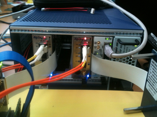
Am trying CPRI test between DSP to, but I can not do it.
Answer?
Test board AMC-2C66-3AIF Card
http://www.commagility.com/amc-2c6670.php
Thanks,
Best Regards
gyosun