


We use a CMOS image sensor which can perform 2x and 4x binning of pixels. The sensor (MT9P031) averages blocks of Bayer pixels as shown below (e.g. x2 binning in x and y).
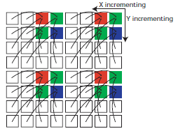
With this method of binning, the centroids of the averaged G1, R, B and G2 are not in the same locations as for a non-binned Bayer pattern. That is, even though the number of pixels averaged is 2*2, the spacing between the centers of the averages pixels is still 1 pixel.
This means that there is an effective offset between each of G1, R, B and G2 entering the ISIF / IPIPE. Since the pixels are not in their expected locations, the result is a loss of resolution. This is more noticeable in the luminance, since the G1 and G2 pairs become misaligned leading to a staircase effect (odd and even fields are slightly shifted horizontally, relative to each other).
This could be catered for by applying a shift to each pixel type, as it passes through the ISIF or IPIPE.
I can't determine if there's any facility in the DM365/8 to apply spatial shifts to each Bayer pixel type, as it passes through the pipeline.
Is anyone aware of any facility in the DM365/8 to perform such a correction, or is there a technique to perform a correction by using features such as using interlaced pipelining, CSC matrix, ISIF input buffering?
Is a facility to do such a correction available in the new DM385 processors?
Thanks for any advice.