


On my BeagleBone board I am performing some tests on PRU1 and see some unexpected results.
My program:
L_MODE5_WAIT_0:
QBBS L_MODE5_WAIT_0, R31.t13 // wait until input => '0'
CLR R30.t10 // set output low
L_MODE5_WAIT_1:
QBBC L_MODE5_WAIT_1, R31.t13 // wait until input => '1'
SET R30.t10 // set output high
JMP L_MODE5_WAIT_0
On R31.t13 a block signal of 10MHz is present. In this program I try to follow this input with output pin R30.t10
On a scope. I see this picture:
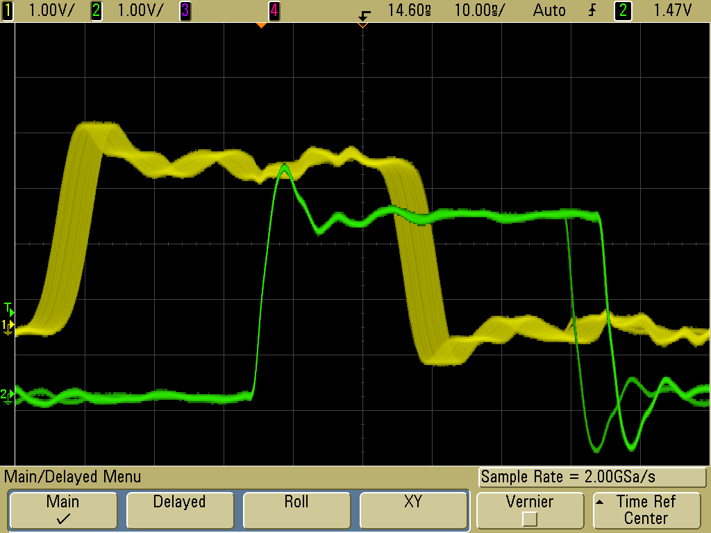
The yellow trace is the input signal on R31.t13, and the green trace is the output on R30.t10.
Since the input signal is asynchronous with respect to the PRU clock, 5 ns jitter is present.
What puzzles me is the delay of 25 ns between the input and the output.
From chapter 25.3.4.3 of the technical ref (Literature Number: SPRUH73G) I read that probably two clocks are lost before a change on a gpio pin is clocked in. This would account for 10 ns, so I still have 15 ns unexplained.
Questions:
- how can this measurement be explained (the missing 15 ns).
- 1) I have not been able to find more info about execution times of PRU assembly instructions; is there a document containing this info?
- 2) I have performed a similar test by polling the MSR of UART0 that is present in the PRUSS. Here the results are even more dramatic. It will last between 60 and 135 ns before the output follows the input. Partially this will be due to the extra instruction needed to read the register (LBCO R1, C7, 0x18, 1), but that does not explain the additional 35 ns with respect to the first test. Could it be that the UART runs on another clock?
- 3) also, the jitter of the second test is 75 ns. Does that mean that the LBCO instruction can take up to 75 - 5 = 70 ns?
Below code and picture of 2nd test
L_MODE5_WAIT_0:
lbco r1, C7, 0x18, 1
qbbs L_MODE5_WAIT_0, r1, 4 // input = '1'? (note CTSn inverts)
SET R30.t10 // set output high
L_MODE5_WAIT_1:
lbco r1, C7, 0x18, 1
qbbc L_MODE5_WAIT_1, r1, 4 // input = '0'? (note CTSn inverts)
clr R30.t10 // set output low
JMP L_MODE5_WAIT_0
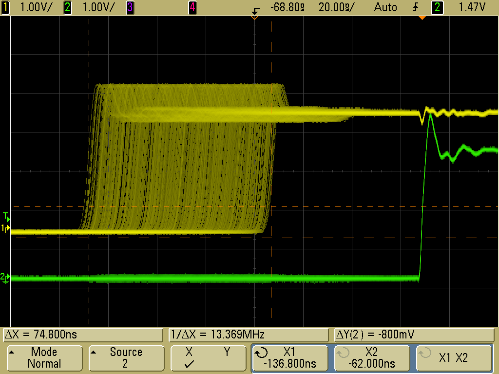
Yellow: input on UART0_CTS (1 MHz block)
Green: the output on R30.t10.
