


Hi, everyone
I’m using TMS320C6747 as the main CPU of a power system control device. There have about 500 devices running on site. All these devices already continue running and operation normal for about 1.5 year.
But recently, many device got fault on EMIFB SDRAM access. Check the devices, we found there have a mistake installed resistor on EMIFB SDRAM clock signal line, like this:
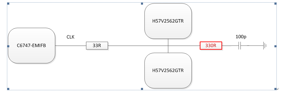
The 330R resistor is used for test only, but mistake installed in product.
We use 1G Hz wave scope( with 1G probe) check the fault board, and compare to the new board, found the single waveform is various between fault board, same among new board( all waveform is got from no 330R resistor and 33R resistor is set to 0R):
waveform samples (1V / Div on Y, and 2nS /Div on X):
the 2 red line/arrow at the bottom of picture indicate 2 fault board,
the top red line/arrow at the top of picture indicate new board waveform
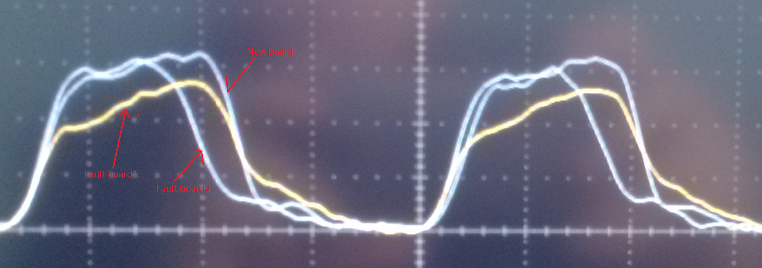
The fault board‘s wave width or amplitude is changed.
So we think the EMIFB clk pin’s load capability can’t drive the 330R load, in order to solve the problem, we remove the 330R resistor. We find:
- For all new or short run devices, there have no any problem.
- For the device already running for 1 year or more that currently running normally, when remove the 330R resistor, the devices got fault, so we can’t remove the resistor to fix the problem, the only we can do is replace the DSP chip.
My question is:
- Is the TMS320C6747 EMIFB clk pin 330R load is too heavy? That causes the clk pin broken.
- Why remove the resistor can’t fix the problem for current run normal devices?
Is there somebody have any sense about this?
Thanks very much!
Cheng Li.


