This thread has been locked.

If you have a related question, please click the "Ask a related question" button in the top right corner. The newly created question will be automatically linked to this question.

C5505 EMIF pin grounded = excessive power consumption?

Other Parts Discussed in Thread: TMS320C5505

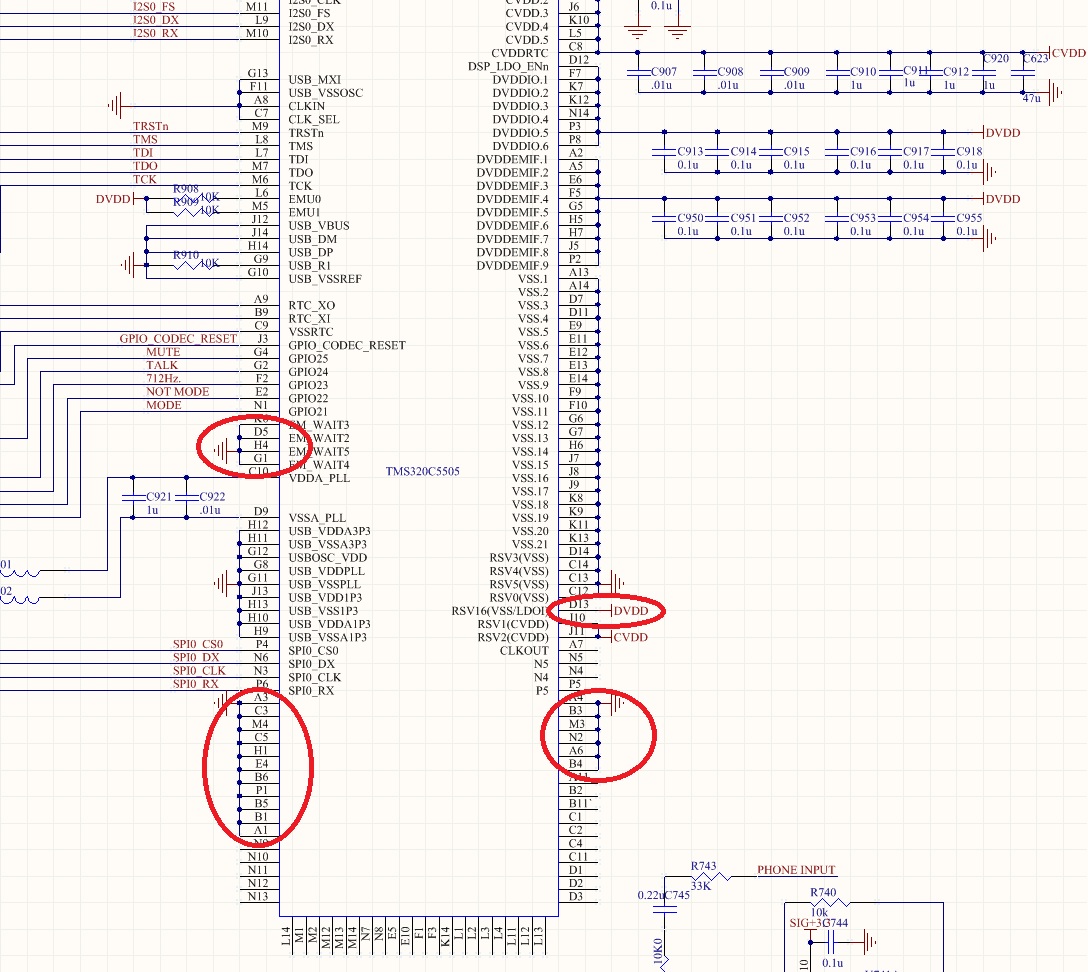
A contractor developed a circuit board for us based on the TMS320C5505 USBStick, but he grounded all these pins (EMIF DDVDD tied to 3.3V).  The board is not usable at all as  the DSP consumes excessive amount of current and as expected it get very  warm.  Could anybody suggest if grounding directly those pins causing the problem?  There is no shorts between the 3.3V and gnd.

EM_CS5
EM_CS4
EM_CS3
EM_CS2
EM_WE
EM_OE
EM_R/W
EM_DQM1
EM_DQM0
EM_BA[1]
EM_BA[0]
EM_WAIT5
EM_WAIT4
EM_WAIT3
EM_WAIT2
EM_CS1
EM_CS0
EM_SDCLK
EM_SDCKE
EM_SDRAS
EM_SDCAS

  • Can you try removing all the DVDDEMIF connection to 3.3v and ground one of the DVDDEMIF pins? This would determine is there a path. Quite frankly, there could be other cause to the current consumption.

    Regards.

  • I need DVDDEMIF connected since I am using GPIO 21 - 25 which are powered by DVDDEMIF.


  • Aren't these pins tied directly to ground without termination resistors? How can they toggle?

  •  


  • Last message didn't send properly.

    Please see the attachement, Steve.

  • I've removed all the pins circled in read from ground, except the D13, but the problem still there.  Could anyone advise where the problem could be?

    CVdd is ok, but Dvdd brings down the supply voltage .   There is no short between DVDD and Gnd.  Resistance between DVDD and Gnd = 10K.

    Thanks.

  • I can see a few issues that would cause high power consumption.

    1) After you removed those pins from ground, are they leave floating? Floating pins will cause high power consumption. Please refer to this page for ways to handle the pins.

    http://processors.wiki.ti.com/index.php/C5000_DSP_based_Low-power_system_design

    2) D13 is tied to DVDD, what is the voltage of DVDD? We recommended RSV16 be tied to GND or LDOI in data sheet.

    Regards.


  • LDOI is also connected to DVDD, which seems valid for D13 to connect to DVDD.  DVDD is 3.3V.

    TI's USBstick design actually left the EMIF control pin floating.  I was suspecting the problem was connecting directly those pins to ground, but it seems the problem is somewhere else.

  • Please always refer to data sheet. Despite the designer's best efforts, the EVMs may contain errors which may still function but are not completely aligned with the datasheet specification. In case of any discrepancy between the TI EVMs and the device datasheet, always follow the datasheet. Therefore the EVM designs should not be considered as reference designs to be blindly reused.

  • Steve/TI,

    I see.  Thanks for  the advice.  I used to trust reference designs very much, especially the designs from the manufacturer of the device.  

    I have never used TI DSP before and I am left with a legacy design which does not work at all, and now I’ve exhausted my options here.   I am not concerning about little leakage current as suggested in WIKI, the problem I am facing is the DSP consumes excessive current of up few 100 mA, without even being programmed and connected to other ICs.  I am not trying to optimise it, instead  just want to get it to run without kill the power supply.

    Could you have another look at the schematic I posted  a few days before and advise me the most likely cause?     I tried to power DVDD (3.3V)  without CVDD (1.3V), the problem goes away, reconnecting CVDD problem comes back!    However CVDD works happly by it self. 

    Ben

  • Ok. Let's focus on functionality. If your contractor designed the board based on the C5505 eZdsp, then you can be sure that the chip can function with those pins floating and is not consuming few 100mA. Even with all pins floating, it cannot be in the 100mA range.

    Based on your new data, I would suspect a leakage path between CVDD and DVDD. There could be short between the board's power traces. Also recommend contacting local TI FAE for assist.

    Regards. 

  • CVDD and DVDD is high impedance.    Contact local TI FAE without any luck.

    Is there anyone within your department that you could forward my schematic to and verify my connection quickly. 

    I don’t need  optimisation suggestions, I just need a straight answer.  Assuming the PCB is manufactured correctly, and all the I/O digital connections are problem free.  Problem must be at the power pins...??????

    DVDD = 3.3V and CVDD = 1.3V .  TI linear regulator used TPS76601 for both power suppliers


  • I wish I can give a straight answer now. However, your problem requires a detail schematic review and board debug. There are procedures and checklist for local FAEs to follow through.

    Regards.