This thread has been locked.

If you have a related question, please click the "Ask a related question" button in the top right corner. The newly created question will be automatically linked to this question.

Several questions about C55 instruction in debug

Other Parts Discussed in Thread: TMS320VC5505

Hi,

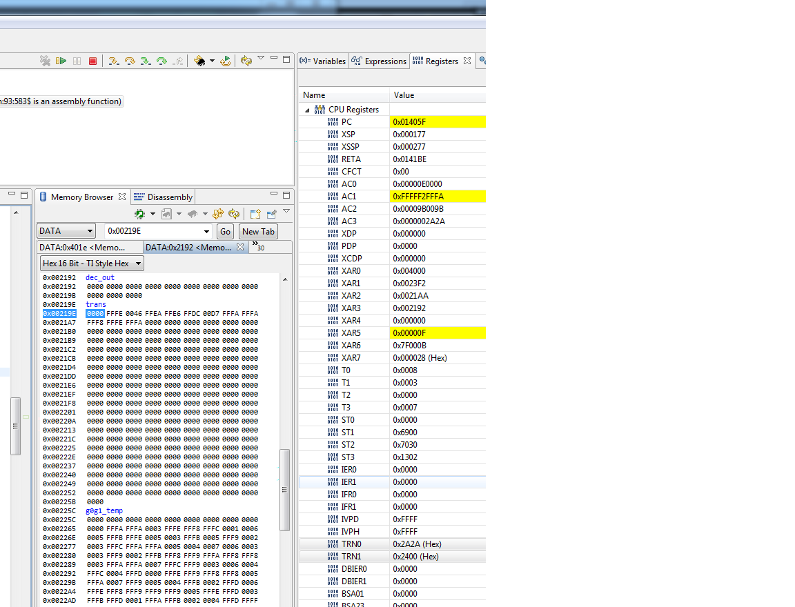
When I debug my code, there are several questions I cannot find the answers. In the following figure, when I stop at line 327, it seems to me that AC1 and AC3 should have the same results as TRN1 and TRN0 (by *AR6 and *AR7 as the comment says). In fact, AC3 is the same with TRN0, but AC1(ignore high 6 bits. fff2h) is not the same with TRN1(2400h). At the XAR6 address(7f000b) content is that of TRN1, i.e. 2400h. At the XAR7 address(000028h) the content is that of TRN0, i.e.2A2Ah. 

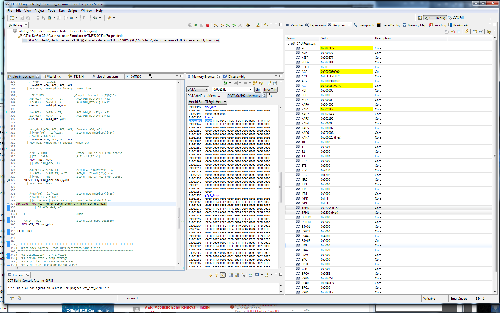
Then the logic of line 336 is the combination of AC1 and AC3 after AC3 left rotation 8 bits. But either with the TRN0, TRN1, or AC1, AC3, I cannot get the result of FFFA in AC1 after the bits combination. What is the problem with the unexpected results?

Thanks,

  • Hi,

    At the beginning of the code, there is such lines on AR6 and AR7:


    MOV #AC1_L, AR6 ;Absolute date memory access to MMR
    MOV #AC3_L, AR7 ;register. AR6 points to AC1 and AR7
    ;points to AC3

    After execution:

    ;*AR6 = TRN1 ;Store TRN1 in AC1 (MMR access)

    ;||T3 = *AR2- ;A=Insoft(2*j+1)
    MOV TRN1, *AR6
    || MOV *sd_ptr-, T3

    AC1 register has the data of TRN1? In the register window when debug, AC1 content is not that of TRN1.

    ;hi(AC0) = *(AR2+T1) + T3, ;AC0_H = INsoft(2*j) + A
    ;lo(AC0) = *(AR2+T1) - T3 ;AC0_H = INsoft(2*j) - A
    ;||*AR7 = TRN0 ;Store TRN0 in AC3 (MMR access)
    ADDSUB T3,*(sd_ptr+index),AC0
    ||MOV TRN0, *AR7

    In my debug process, AC3 does have the same content of TRN0. Why are there different results for the above similar line execution?

    ;*AR4(T0) = lo(AC2), ;Store New_metric(7)&(15)
    ;*(AR4+T0) = hi(AC2)
    ;||AC1 = AC1 | (AC3 <<< #-8) ;Combine hard decisions
    dec_loop: MOV AC2, *mnew_ptr(m_index), *(mnew_ptr+m_index)
    || OR AC3<<#-8, AC1

    I do not see AC1 content is the combination of AC1 and shifted AC3. What is the problem? The above code is downloaded from the companion code of spra776a.pdf. Thanks,

  • Hi,

    spra776a.pdf title is for TMS320C55xx DSP. I suppose it can apply to TMS320VC5505 DSP because I have its document on the computer. This doc said that the first 192 bytes is for MMR. Then, I check AR7 content is 0x000028, which is in the range of 192 byte. AC3 does have the same content of TRN0. AR6 is 0x7f000b, which is out of range 192 byte. AC1 has different content of TRN1.

    A further question is about AC1_L. Where is this constant defined? The MMR configuration is wrong (I did not modify anything except create this target).

    I use target: C55xx Rev3.0 CPU Cycle Accurate Simulator of CCS 5.2.1.00018, Windows 7 OS, 64 bit. Anything I can change? What simulator target is appropriate for this Viterbi target from spra776a.pdf?

    Thanks

  • I find that although new C55 chips documents mentions 192 MMR, there is no detail what registers it supports. What documentsIf spra776a.pdf was limited to the old C55 chips, how can I use the new C55 chip by modifying the code. At least I want to it functional changes to new coding (by not caring about performance).

    After execution:

    MOV #AC1_L, AR6 ;Absolute date memory access to MMR
    MOV #AC3_L, AR7 ;register. AR6 points to AC1 and AR7
    ;points to AC3

    AR6 has content: 0x7f000b. This has problems with MMR?

  • Hi,

    When I check in disassembly window, I find that AR6 is 0x7FFFFF before


    MOV #AC1_L, AR6 ;Absolute date memory access to MMR

    MOV #AC3_L, AR7 ;register. AR6 points to AC1 and AR7 ;points to AC3

    At disassembly window, it has this format:

    MOV #11, AR6 ;

    MOV #40, AR7 ;


    It seems that the first 8 bits (0x7F) are segment like thing. Does it care or not in MMR of AC1 usage? (It has to reset to 0x00?)

    Thanks,

  • C55x is a complicated architecture, with complicated addressing modes, and a complicated pipeline, and it's been a long time since I was very familiar with all of this.  Let's take this slowly so that we can make sure there is no misunderstanding.

    The instruction

    MOV #AC1_L, AR6

    is not a memory access.  It strictly loads the MMR address of AC1_L into the register AR6.  AR6 is the 16-bit portion of the 23-bit register XAR6.  The instruction you've used is a 16-bit execute-phase register move, so it cannot modify the upper bits of XAR6, which it leaves alone.  You must either take care to clear the upper bits of XAR6 before this instruction, or use the appropriate address-phase move instead.  One way to do this would be with this instruction:

    AMOV #AC1_L, XAR6

    However, none of this explains why the upper bits of XAR6 were non-zero to begin with.  Are you using large memory model?

  • Hi,

    I do not need large memory model. Your answer solves the proble. Thanks.

  • Hi,

    Here is a further question on the problem. Why does AR7 not need AMOV instruction? even though AR6 runs first for the instruction:

    MOV #AC1_L, AR6 ;Absolute date memory access to MMR

    MOV #AC3_L, AR7 ;register. AR6 points to AC1 and AR7 ;points to AC3


    I have check the compiler option, and do not find an option can change the memory model. Is there such one ?

    Thanks,


  • Both instructions would need AMOV.  You were just lucky that XAR7 had 0 in its upper 7 bits; this is not guaranteed.

    Robert W said:
    I have check the compiler option, and do not find an option can change the memory model. Is there such one ?

    Yes.  See section 6.1 "Memory" in TMS320C55x Optimizing C/C++ Compiler v4.4 User's Guide (SPRU281G) http://www.ti.com/lit/ug/spru281g/spru281g.pdf