This thread has been locked.

If you have a related question, please click the "Ask a related question" button in the top right corner. The newly created question will be automatically linked to this question.

C5535 VBUS detection does not work?

Dear support staff

We are working on a device based on the C5535. It seems that when we read the DEVCTL register, the result is always 0x0099 (indicating VBUS_Valid), irrespective of whether the USB bus is present or not.

USBSCR is initialized with 0x2040, so the VBUS detector should be On.

Also the disconnect interrupt or session end interrupt are both not working (probably the same origin...).

In other words, the device has no way of knowing whether or not it is connected to a USB bus...

Is this is known bug?

Thanks

Bruno

  • Bruno

    There is a clock gating bit for USB module from the system clock point of view. It is the USBCG bit in 0x1C03, are you setting this bit correctly? Also, what is your system PLL frequency for USB?

    Thanks
    David

  • Hi David

    Yes, USBCG is set to Active in PCGCR2. Besides, apart from that VBUS detection problem, the USB module is working completely.

    The system PLL is set for a frequency close to 100 MHz (100.007936 MHz). That comes directly from  the devkit examples.

    Bruno

  • Bruno

    Are you saying that when there is no 5V on VBUS, you are still seeing DevCtrl register being 0x99?

    Thanks

    David  

  • Yes David

    That is exactly what I am saying

    Bruno

  • Bruno

    Are you using your own board or TI EVM? Have you phyiscally checked the VBUS and make sure there is no voltage on VBUS? The VBUS_VALID in DevCtrl register is working correctly, there is no bug associated with this.

    Thanks
    David

  • Hi David


    I am using our own board. I do not think that the C5535 EzDSP can be used to demonstrate this problem easily because it is bus-powered. When VBUS is off the whole board is off...

    I checked that VBUS on the DSP pin was at 0 V phisically, and was still reading 0x99.

    I am not saying that it is a silicon bug. It is possible that I am doing something wrong, but what could lead to that behaviour? As I said I have verified that the VBUS detector is On...

  • Bruno

    Can you please use TI CSL code instead your own code on your board? This would help separating the issue between SW and HW. I verified the DevCtrl register is working correctly as expected. 

    Thanks

    David

  • Hi David

    I did some more tests. One problem came from a diode leakage that prevented the VBus from going all the way down to zero when the cable was disconnected. It came to between 2 and 3V, depending on the board temperature. After realizing that, I did two additional tests:

    - The first test was to cool-down the diode in order to reduce the leakage. This in turn allowed the VBUS voltage to go down to zero in a controlled manner, as a function of temperature. What I found out is that the DEVCTL register stays at 0x0099 (indicating "Above VBUS Valid") until the VBUS voltage goes below 1.5V...! At this point DEVCTL reads 0x0090, which indicates "Above A-Valid, Below VBUS Valid". When VBUS rises to above 3V the DEVCTL stays at 0x0090. It only switches back to 0x0099 when the VBus voltage is close to 5V. In other words there seems to be a HUGE hysteresis...

    Is that normal? I would have expected an hysteresis of at most 100 mV. A Hysteresis of more than 3V seems very abnormal, and to defeat the purpose of this input!

    - The second test that I did was to place a 10k pull-down between VBus and ground, to force the voltage to drop lower, despite the diode leakage. A 10k pull down on VBus should not pose any problem. In that situation I find the strangest behaviour:

     1) Everything seems normal with respect to USB communications when VBUS is present.

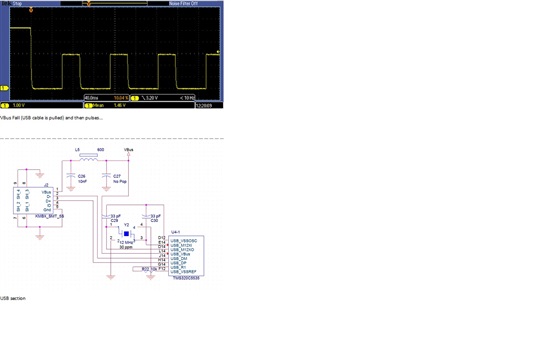
     2) When VBUS is removed, the VBUS voltage first drops to a few hundred mV, as it should. Then it pulses at 2.8V, for 32.8 ms, every 91 ms, as if VBUS was driving the bus...!

    I have not found anything documented that could explain either the large hysteresis or the behaviour when a pull-down is added on VBUS.

    Is there anything to explain that?

    Thanks

    Bruno

  • Bruno

    There are different levels of VBUS voltage comparison:

    For VBUS bits to be 0x11, VBUS voltage needs to be above 4.4V.

    For VBUS bits to be 0x10, VBUS voltage needs to be between 2V and 4.4V.

     Is it possible to remove the diode and repeat the experiement at normal temperature? This would remove the diode leakage and temperature effect.

    For question #2, C5535 has a USB OTG controller which supports both dataline pulsing and VBUS pulsing as a way to wake up the host, From the description, it looks like VBUS pulsing. If you clear the SESSION bit of the DevCtrl register, I think you would see the VBUS pusling stop.

    Thanks

    David

  • Hi David

    Regarding problem No 1: I found a single place where the SESSION bit was written to 1 in the USB init function (that is my code, but was the same in the EzUSB example). I tried to remove the line, I see no behaviour difference. I even tried to force the SESSION bit to zero instead of one. I saw no difference. I am suspecting a timing problem, maybe, but it is a bit difficult for me to debug that since there is no documentation about any of that behaviour anywhere...

    Regarding problem No 2: The behaviour is very strange:

    1) if the voltage is changed gradually between 0V and 5V, the VBUS code changes from 00 to 01 at 0.5V. Then it changes from 01 to 10 at 1.4V. Then it never goes to 11, even if the voltage goes above 5V...!

    2) if the voltage is changed sharply from 0 to 5V, the code indeed goes to 11. But then if the voltage is ramped gradually back to zero, the code changes directly from 11 to 01 at 1.4V. It never passes through 10. Furthermore, the code stays at 01 (never goes to 00), even though the VBUS voltage goes down to 0V!

    It seems that the VBUS code is affected by the rate of change on the pin, not just the voltage value. In practice it is possible to insure a sharp rise to some extent, but almost impossible to insure a sharp drop to zero. The rate of fall of the pin voltage when the pin is floating is affected by the capacitance on VBUS and the pull-down value. A low resistive pull-down cannot be implemented because it would drain VBUS current while in suspend.

    I saw no documentation about that anywhere...

  • Bruno

    For problem #1, are you saying that when SESSION bit is cleared, you are still seeing VBUS pulsing?

    For problem #2, VBUS rise time is required to be within 100ms per the USB OTG spec, are you meeting this spec?

    With the discovery of diode leakage issue, are you seeing the DISCONNECT and SESSEND interrupt working correctly now?

    Is it possible that you can share the USB portion of the schematic (in pdf) and scope capture with me?

    Thanks

    David

  • Hi David

    For problem #1:

    Even after I write 0x0000 to DEVCTL, the SESSION bit still reads 1 (from the description in the user's manual I think that is normal), AND the VBUS still pulses when the USB cable is pulled (I think that is abnormal). By th2860.VBus_Detection_Problems.pdfe way, the pulsing does not occur all the time. Sometimes the line stays low.

    When the line pulses the VBUS detection logic does not work (i.e. when read the VBUS bits of DEVCTL read 11, even though the USB cable is off).

    For problem # 2:

    I have no problem insuring that the VBUS rise time is short and <100ms. However the fall time depends on the amount of capacitance on the pin and the value of the resistive pull-down if any. A low resistive pull-down is not possible as I explained earlier because it would drain VBUS current in suspend, which might be in excess of what the USB spec allows. We therefore may have to live with a slow fall time, and as I showed earlier the VBUS detection logic does not seem to work properly during a slow fall either...

    I added the JPG below. In this case, the capacitor C27 has been replaced by a 100k resistor in order to shorten the fall time and insure a return to 0V. Otherwise the pin is completely floating and may not fall all the way to zero. Let me know if you would prefer a pdf showing the same.I could not find any way to upload a pdf.

  • Bruno

    The SESSION bit is read/writable, are you writing to register address 0x8461h?

    I took a look at the schematic, and the USB interface implementation looks correct. Two experiemnts I would suggest:

    1. Use the TI CSL code on your board and see if the problem is duplicable

    2. Remove the diode and short across the diode pad, this makes sure the diode is not part of the issue.

    Thanks

    David

  • Hi David

    Yes, I write 0 at address 0x8461. From what I understand (spruh87c.pdf page 487), the SESSION bit is RW, but what you read is actually the session state, while you write 1 to start the SRP. Therefore I do not expect to read 0 after writing 0... Although the documentation is very slim on the subject, so my interpretation may be wrong.

    In any case regarding problem #1

    I think we have the culprit. We switch all the PLLs Off while in suspend in order to reduce the suspend current to the allowable level. If we leave the PLLs ON while in suspend, the problem does not occur. However in that case we do not pass the suspend current requirements anymore...! Therefore the question becomes "how to switch-off the PLLs without triggering the VBUS pulsing at the next VBUS removal?"

    Regarding problem #2

    The diode is not shown on the diagram that I sent, and indeed it was removed for the latest tests that I did (my previous message). So the schematic IS representative of the actual USB input configuration during the latest tests. There is no more diode leakage because there is no more diode. However the behaviour is what I described when the VBUS falls slowly (VBUS level only switches from 11 to 01 when VBUS falls below 1.4V. The code never goes through 10. The code never goes to 00, even if VBUS goes down to 0V.

  • Bruno

    You can set the SESSION bit to a 1 to start the session, and also a 0 to stop the session. When you write a 1 to the SESSION bit and if the VBUS is not present, it will initiate a session request by pulsing DP and VBUS. If the VBUS is present, it will enable the internal pull-up resistor on DP to signal connect event to the host.

    You can turn all the PLL off except the PLL to the USB controller. The USB controller needs to have the clock in order to detect resume/reset condition on the USB bus to wake up. If you turn off PLL except the USB PLL, how much current are you seeing on VBUS? Is this a bus-powered or a self-powered application? Also, are you setting the ENSUSPENDM bit when you got the SUSPEND interrupt?

    For problem #2, I need some time to work on it as I haven't seen this issue before.

    Thanks

    David

  • Hi David


    Problem #1:

    Sorry I was not very clear. We DO NOT switch off the USB PLL when entering suspend (obviously the USB would not recover at all at resume time...) We only switch off the system PLL (CCR2, CGCR1, CGICR, CGCR2, and CGOCR registers). When we switch off the system PLL when entering suspend, and restore it when leaving suspend, the only observed problem is that the VBUS line pulses when VBUS is removed subsequently. Somehow, stopping and restoring the PLL seems to affect the Session Request Protocol...

    Regarding the SESSION bit. Now I am confused... I thought the internal pull-up was enabled by the SOFTCONN bit in the POWER register. We NEVER write a 1 in the SESSION bit while VBUS is Off. Besides, I tried to NOT write anything to DEVCTL at any time, that does not change anything to the observed pulsing behaviour. The ONLY thing that seems to affect that behaviour has been to avoid stopping the system PLL during suspend.

    We have yet to make precise suspend current measurements, but the data sheet indicates that the system PLL is responsible for 0.7 mA of current, which is not negligible, even with the increased 2.5 mA allowance.

    Problem #2:

    OK, thank you for your help on this.'

    Regards

    Bruno

  • Bruno

    The SOFTCONN allows the connection to the USB bus to be controlled by software. When this bit is set to 1, the USB PHY is placed in normal mode and D+/D- lines of the USB bus are enabled. When this bit is set to 0, the USB PHY is placed in non-driving mode.

    On the problem #2, I don't see a reason why the VBUS bits are not getting updated. Are you doing multiple reads once the VBUS voltage reaches above 4.4V? Is the USB in its normal mode?

    Thanks

    David

  • Hi David

    I understand. Once SOFTCONN is set, the USB PHY will automatically set the SESSION bit and connect the D+ pull-up upon VBUS detection. But that does not mean that SOFTCONN drives the pull-up - Understood.

    That does not change the observed behaviour. Even when DEVCTL (and therefore SESSION) is not written at all, we still see the VBUS pulsing behaviour when VBUS is disconnected, if (after) the system PLL has been stopped during suspend and restarted at resume. That pulsing behaviour is not seen when the system PLL is kept On through suspend.

    On problem #2:

    Yes, in the latest tests that I described I was reading DEVCTL repeatedly in a fast loop (> 100 times a second) while slowly varying VBUS voltage with a voltage source. In one test I started at 0V and went-up to 5V, then back down to 0V. In another test I went sharply from 0V to 5V (by switching the source On), then slowly back down to 0V.

    Yes, the USB was in normal mode. Not only that, but when VBUS was detected USB functinoality was complete.

  • Bruno

    I need some time to dig through these two issues. For now, are these two tissues gating your developement?

    Thanks

    David

  • Hi David

    At this point I do not think so.

    Problem #1:

    The design is both bus-powered and self-powered. When it is bus-powered we will need to stop the PLL during suspend, which might trigger the VBUS pulsing behaviour when the USB cable is disconnected, except in that case this is not a problem because disconnecting the cable will obviously kill everything! When it is self-powered we do not have to stop the PLLs (or do anything) during suspend because the power does not come from USB. So my hope is that not stopping the PLL will inhibit the pulsing behaviour consistently every time.

    Problem #2:

    Even though the VBUS bits in DEVCTL do not seem to follow the VBUS voltage properly it seems that when the USB cable is pulled it is at least possible to detect that VBUS is not "ABOVE VBUS VALID" anymore. If that proves true and consistent that is all I need (to distinguish if the cable is present or not).

    I would still like to know the end of this story whenever you have the answer!

    Thanks

    Bruno

  • Bruno

    There is a register called SRPFIXTIME register. If the transition from SESVALID to VBUSVALID happens in the time frame defined by this register, you would never see the transition state. Would you please modify the time frame defined by this register and then see if you can observe the transition state?

    Thanks

    David