This thread has been locked.

If you have a related question, please click the "Ask a related question" button in the top right corner. The newly created question will be automatically linked to this question.

Daisy chained Ethernet

Hi all,

We are developing on a custom board consisting of several C6678 DSPs divided into pairs. Of each pair, one is directly connected to a Marvell network switch via SGMII and the other is daisy-chained through the first. (The network switch has a PHY connected to one of its ports to enable external communications. None of the DSPs are directly connected to a PHY.) Here is a crude diagram of one such pair:

<Marvell Switch> --- <SGMII0 – DSP1 – SGMII1> --- <SGMII1 – DSP2>

So DSP 1 sees the network switch through SGMII0 and is connected to DSP 2 through SGMII1. DSP 2 is connected to DSP 1 on its SGMII1 and has nothing connected to its SGMII0.

This is different from the EVM, where the DSP has a PHY on port 1 and port 0 leads to the external AMC connector. So we need to modify some software components that were built specifically for the EVM - hopefully just the platform lib.

Our platform lib for this board is based on the EVMC6678 version. We’ve modified the function platform_init such that it inits SGMII0 only on DSP 1, and SGMII1 on both DSPs. Function call Init_SGMII for port 1 returns properly on both DSPs, detecting a successful link and autonegotiation with the opposing device.

The NIMU driver (part of the 6678-specific PDK, used by the NDK) calls the platform lib’s platform_get_emac_info function to query the MAC address, and also to discover which port it should access. It seems to ask the platform lib which of the ports is connected to a PHY (as opposed to the AMC) then assigns the number of that port to a variable named gTxPort.

We modified the platform lib such that on DSP 1 port 0 will be declared as the PHY, and on DSP 2 port 1. This doesn’t seem like a correct solution because on DSP 1 both ports are supposed to be active (utilizing the switching capability of the Ethernet module) but it was our best guess. With this code in place, DSP 1 can access the network with no problem, but DSP 2 seems to have a network connection but it lasts very briefly – it is able to ping and receive a connection from the outside world for a few seconds – and then the network stops functioning until the next restart. However, at no time are the two DSPs able to ping each other.

I find it strange that NIMU queries for a MAC address per port. This makes no sense because the DSP is supposed to have just one MAC address regardless of how many ports its internal switch has. Perhaps I'm misunderstanding something.

In any case, any ideas on getting this daisy-chained architecture working properly would be most welcome.

Thanks,

-itay


  • I have made some progress, which I will describe here.

    The first thing I wanted to check was that the hardware is wired correctly. I did this by changing the boot mode to Ethernet boot (via dip switch setting) and checking that BOOTP requests were seen on the network. Sure enough, requests from both DSPs were being sent, so electrically we're fine.

    The next step was to find out what part of the software was breaking the connection between DSP 2 and the rest of the network. So while DSP 2 was still sending BOOTP requests I loaded up my networked application to DSP 1. It seems that the platform lib's platform_init was not doing a correct job, as the BOOTP from DSP 2 was still not being seen after calling it. Imitating the actions of the ROM bootloader (in case Ext Connection dip switches are set to 2, "Mac to Mac, forced link" - see sprugy5 Table 3-8), I changed the platform lib to set both SGMII ports to "SGMII to SGMII with Forced Link Configuration" mode (see sprugv9 section 2.4.3.4). With this change, platform_init completes with the packets from DSP 2 still being seen on the outside network.

    Moving on, DSP 1 calls NC_NetStart to start its network stack, at which point again DSP 2 loses network connectivity. Looking into the issue, the disconnect happens when nimu_eth function Init_Cpsw runs, initializing the switch differently from the way we need it. I removed the call to this function, and almost everything seems to be working.

    By 'almost' I mean that both DSP 1 and 2 can now load the network stack; they are both able to talk to the outside world (pings work both ways); but they are unable to ping each other. Any assistance with this final problem will be most appreciated.

    Thanks,

    -itay

  • I've been trying to understand how the boot loader configures the networking hardware by analyzing its source code. In bootloader source code file hw/sgmii/sgmii.c there are three writes to SGMII registers TX_CFG, RX_CFG, AUX_CFG. These registers are part of the SGMII module documented in sprugv9b section 3.3. However these three registers are undocumented! Table 3-5 in page 3-9 details the registers of the SGMII module but lists the address range 24h-7Fh as "reserved"; the registers named above are located at 30h, 34h and 38h respectively. They even have APIs enabling access to them (in the C6678 PDK, file csl_cpsgmiiAux.h: CSL_SGMII_setTxConfig, CSL_SGMII_setRxConfig, CSL_SGMII_setAuxConfig) but there is no information on what they do.

    The values written by the boot loader to the TX_CFG and RX_CFG registers seem similar in format to those written to the CFGTXn and CFGRXn in the SerDes SGMII Boot Configuration registers (same document, section 3.6) in the platform lib's SGMII initialization. However I don't understand the connection, if there is one, between the two sets of registers. Also, the boot loader writes the value 0x229 to the AUX register - I haven't been able to figure out what this does at all.

    Is there any information on these registers anywhere?

    Thanks.

  • Itay,

    TX_CFG, RX_CFG and AUX_CFG are SERDES configuration registers. In previous generation of devices (i.e. before Keystone family) they were part of SGMII module and so those registers were part of SGMII memory map. With Keystone family, SERDES registers are moved to SoC level memory map as CFGTXn and CFGRXn. They are no longer part of SGMII module. So the register write in SGMII.c of bootloader at SGMII memory maps for SERDES registers will not have any effect. Although I still need to check why they are still there. The register configuration in platform lib is the correct configuration at the SoC level memory map.

    Now for debugging your issue with DSP1 communication with DSP2, lets try to find out where is the packet being dropped OR whether it is really dropped? We can check that by verifying the statistics registers at ethernet switch to see whether the packet which is being sent for DSP2 is really reaching to Switch sub-system or not. You can send packets to DSP2 and check statistics registers to see if you see any change in the statistics or not. I am attaching a GEL file which can help you viewing/monitoring those registers easily.7725.cpsw_stats_print.gel

    In parallel to above effort, we have already started testing here with that scenario. I will get back to you on next two days for this.

    Regards,

    Bhavin

  • Thanks for the GEL file. It took me a while to figure out what was going on - the GEL outputs stats for "Ethernet A" and "Ethernet B". Ethernet A is the side of the internal switch facing the DSP and Ethernet B is the side facing the device's two output ports. So, a packet successfully sent from DSP 1 to DSP 2 would show up as received by DSP 1 Ethernet A, sent by DSP 1 Ethernet B, received by DSP 2 Ethernet B, sent by DSP 2 Ethernet A.

    From looking at the stats it is clear that packets sent from DSP 2 to DSP 1 are received by DSP 2's switch, sent out and received by DSP 1's switch and sent in to DSP 1. Packets from DSP 1 to DSP 2, on the other hand, are received by DSP 1's switch and sent out, but DSP 2's switch completely ignores them or perhaps never sees them - there is no change in the value of any statistics register at all.

    I am attaching the following logs, containing before and after register values of both DSPs in the following 3 scenarios:

    1. DSP 1 pings DSP 2, while DSP 2 is halted
    2. DSP 2 pings DSP 1, while DSP 1 is halted
    3. DSP 2 pings DSP 1, while DSP 1 is running idle (it seems to respond to the ping, but DSP 2 does not get the response)

    5700.pings.zip

    Apparently communications between the DSPs are working in one direction only (from 2 to 1). Any ideas on fixing this? (Remember that this is not an electrical problem as DSP 2 has no problems communicating with other network hosts. When connecting the board to the corporate network the DSP 2 RX Good Frames begins to rise on Ethernet B due to receiving various broadcast packets from the rest of the network.)


    Thanks,

    -itay

  • Itay,

    I have just reviewed logs for Ping1 and here are my inputs.

    1.DSP 1 pings DSP 2, while DSP 2 is halted [Bhavin] - It is visible that nothing is getting received by DSP2. Although we don't know whether the transmit statastics (Statistics B) of DSP1 are for SGMII0 or SGMII1. They might be for SGMII0 and nothing is really getting transmitted out of SGMII1 so nothing is going to DSP2. There is one register which controls whether Statistics B are for SGMII0 OR SGMII1 OR SGMII0+SGMII1. I have updated GEL file which will tell you the status of that register. This register also controls the enabling and disabling of the statistics for SGMII0 or SGMII1 for Statistics B. With the help of that we can first disable the statistics for sGMII1 which is going to DSP2 to identify whether the results of Statistic B is still same as before. If it is same as before then nothing is going to SGMII1 which is going to DSP2. Then we can disable the statistics for SGMII0/Port1 to see whether we can see any increase in Statistics B which will double confirm our results.

    Here is the updated GEL file.3652.cpsw_stats_print.gel

    Regards, Bhavin

  • You hit the nail on the head. When DSP 1 pings DSP 2 it sends outgoing packets on SGMII0 only, so DSP 2 never receives them. Please advise on how to proceed.

    Thanks,

    -itay

  • Itay,

    Can you send status of ALE registers of Ethernet Switch Sub-system? I have added those registers as "ALE_Status" menu in the attached GEL file.

    7532.cpsw_stats_print.gel

    Regards,

    Bhavin

  • Itay,

    We need to check status of above mentioned registers in your application. Your ALE configuration should be one of below two options. For both the options there is a way to send packets out from a defined port. So we will need to check whether your application is following those instructions or not. Here are two ways to send packets out from Port1 and Port2:

    1. Keep ALE in bypass mode ALE_BYPASS is enabled and PORT_STATE in the ALE_PORTCTLx is in forwarding mode.

            ALE_CONTROL = 0xC0000010;   // Clearing ALE table for Init and Enabling ALE & Bypass ALE

            ALE_PORTCTL0  = 0x00000003;    // Configure Port0 in Forwarding mode

            ALE_PORTCTL1  = 0x00000003;    // Configure Port1 in Forwarding mode

            ALE_PORTCTL2  = 0x00000003;    // Configure Port2 in Forwarding mode


    This will allow all incoming packets from Port1 and Port2 to go to Port0. This configuration will allow all outgoing packets to go out either via Port1 or Port2 depending on the protocol specific data field of the protocol specific part of the descriptor. Below are four options I captured from one of my source code:


    host_pkt->psData   = 0x00100000;    //Sending through EMAC1/Port1 out

    OR

    host_pkt->psData   = 0x00900000;    //Sending through EMAC1/Port1 out & pass_crc = 1 so CRC is already in the packet EMAC don’t have to calculate it

    OR

    host_pkt->psData   = 0x00200000;    //Sending through EMAC2/Port2 out

    OR

    host_pkt->psData   = 0x00A00000;   //Sending through EMAC2/Port2 out & pass_crc = 1 so CRC is already in the packet EMAC don’t have to calculate it


    2. Configure ALE in non-bypass mode and PORT_STATE in the ALE_PORTCTLx is in forwarding mode. Then send unicast destination packets to each port:


      &host_wr($ALE_CONTROL ,0xc0000000);    #UnReset ALE and Flush Table
      &host_wr($ALE_PORTCTL0,0x00000003);    #Simple Port setup 0, etc
      &host_wr($ALE_PORTCTL1,0x00000003);    #Simple Port setup 1, etc
      &host_wr($ALE_PORTCTL2,0x00000003);    #Simple Port setup 2, etc

    Now add unicast MAC addresses in the ALE table as shown below:

    # setup port 0 address = 000000000000
      &host_wr($ALE_TBLW2,0x00000000); &host_wr($ALE_TBLW1,0x10000000); &host_wr($ALE_TBLW0,0x00000000); &host_wr($ALE_TBLCTL,0x80000000);
      # setup port 1 address = 111111111111
      &host_wr($ALE_TBLW2,0x00000004); &host_wr($ALE_TBLW1,0x10000011); &host_wr($ALE_TBLW0,0x11111111); &host_wr($ALE_TBLCTL,0x80000001);
      # setup port 2 address = 222222222222
      &host_wr($ALE_TBLW2,0x00000008); &host_wr($ALE_TBLW1,0x10000022); &host_wr($ALE_TBLW0,0x22222222); &host_wr($ALE_TBLCTL,0x80000002);


      &host_rd(0x80000600,$V_ALE_IDVER); #Wait for add to complete


      # Read locations
      &host_wr($ALE_TBLCTL,0x00000000); &host_rd($ALE_TBLW2,0x00000000); &host_rd($ALE_TBLW1,0x10000000); &host_rd($ALE_TBLW0,0x00000000);

      &host_wr($ALE_TBLCTL,0x00000001); &host_rd($ALE_TBLW2,0x00000004); &host_rd($ALE_TBLW1,0x10000011); &host_rd($ALE_TBLW0,0x11111111);

      &host_wr($ALE_TBLCTL,0x00000002); &host_rd($ALE_TBLW2,0x00000008); &host_rd($ALE_TBLW1,0x10000022); &host_rd($ALE_TBLW0,0x22222222);


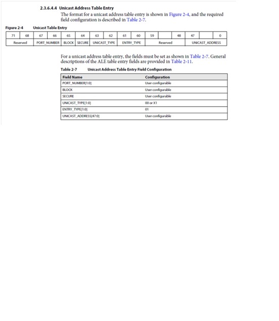
    Here is the definition from user’s guide for adding unicast entry into lookup table:


    Here is the logical view of how we can send packets using unicast MAC addresses:


      # send a packet from port 0 to port 1
      &p0_pkt (1,                 # 0=no, 1=yes on port 1
               0,                 # 0=no, 1=yes on port 2
               '0x001111111111',  # Destination address
          '0x000000000000',  # Source Address
               46,                # LTYPE
               1,                 # Priority
               0,                 # VLAN ID
          46,                # Byte Count
          'INC',             # Packet Type
          1,                 # Seed
               1);                # pass_crc with input packet


      # send a packet from port 1 to port 2
      &p1_pkt (0,                 # 0=no, 1=yes on port 0
               1,                 # 0=no, 1=yes on port 2
               '0x002222222222',  # Destination address
          '0x001111111111',  # Source Address
               46,                # LTYPE
               1,                 # Priority
               0,                 # VLAN ID
          46,                # Byte Count
          'INC',             # Packet Type
          1);                # Seed


      # send a packet from port 2 to port 0
      &p2_pkt (1,                 # 0=no, 1=yes on port 0
               0,                 # 0=no, 1=yes on port 1
               '0x000000000000',  # Destination address
          '0x002222222222',  # Source Address
               46,                # LTYPE
               1,                 # Priority
               0,                 # VLAN ID
          46,                # Byte Count
          'INC',             # Packet Type
          1);                # Seed


    Please let me know if you have any queries or questions.


    Regards,

    Bhavin


  • Bhavin,

    At first the output of the GEL script on both DSPs was:

    GEL Output: CPSW ALE CONTROL ................ 0x80000000
    GEL Output: CPSW ALE PORT0 CONTROL ................ 0x00000003
    GEL Output: CPSW ALE PORT1 CONTROL ................ 0x00000003
    GEL Output: CPSW ALE PORT2 CONTROL ................ 0x00000003

    I then changed the nimu_eth function Init_Cpsw to set ALE CONTROL as you recommended, so the value shown by the script is 0x80000010. Other than that, this change has no effect on the results.

    An interesting point I've noticed is that when the two DSPs ping each other, I can see a single ARP request being broadcast from each of them, but no additional requests. From this I gather that the ARP negotiation is working. However, I could not confirm this as the NDK apparently has no API to query the dynamic ARP table.

    The rest of your message seems a bit daunting. It isn't clear whether your suggestions are solutions or tests, because as solutions they seem unacceptable (the switch is supposed to do this stuff automatically) and as tests they are a little beyond my level of knowledge. I am but a humble NDK user, not a low level network coder, my code doesn't set the protocol headers for packets sent out over the network. I don't know how to use a structure like "host_pkt" or "p0_pkt" - I use sendto() and recv() :) .

    What I have tried however is to use your suggestion from option 2 to manually force the ALE to route packets intended from DSP 1 to DSP 2, through DSP 1's port 2 and vice versa, then run the ping test. My modified version of the nimu_eth function Init_Cpsw is shown below, yet it seems to have no effect whatsoever on the results.

    If you think this test is wrong, please elaborate on how to do the low level packet tests as I really wouldn't know where to start on that.

    Thanks,

    -itay

    int32_t Init_Cpsw (uint32_t mtu, uint8_t* myMACAddress)
    {
        uint8_t   Mac0 [6] = {0x40,0x5f,0xc2,0xb9,0x47,0xcc};
        uint8_t   Mac1 [6] = {0x40,0x5f,0xc2,0xb9,0x41,0x33};
        uint8_t   Dumm [6] = {1,1,1,1,1,1};
        uint8_t   *my_mac, *port1_dest, *port2_dest;;

        if (!memcmp(myMACAddress, Mac0, 6)) // is this DSP 1?
        {
            my_mac = Mac0;
            port1_dest = Dumm; // port 1 is not interesting
            port2_dest = Mac1; // port 2 is other DSP
        }
        else if (!memcmp(myMACAddress, Mac1, 6)) // is this DSP 2?
        {
            my_mac = Mac1;
            port1_dest = Mac0; // port 1 is other DSP
            port2_dest = Dumm; // port 2 is not interesting
        }
        else
            while(1);

        hCpsw3gfRegs->ALE_CONTROL_REG = 0xC0000000;
        hCpsw3gfRegs->ALE_PORT_CONTROL_REG[0] = 0x00000003;
        hCpsw3gfRegs->ALE_PORT_CONTROL_REG[1] = 0x00000003;
        hCpsw3gfRegs->ALE_PORT_CONTROL_REG[2] = 0x00000003;

        // setup port 0 dest address = my own MAC address
        hCpsw3gfRegs->ALE_TABLE_WORD2_REG  = 0x00000000;
        hCpsw3gfRegs->ALE_TABLE_WORD1_REG  = 0x10000000 | (my_mac[0] << 8) | (my_mac[1]);
        hCpsw3gfRegs->ALE_TABLE_WORD0_REG  = (my_mac[2] << 24) | (my_mac[3] << 16) | (my_mac[4] << 8) | (my_mac[5]);
        hCpsw3gfRegs->ALE_TABLE_CONTROL_REG  = 0x80000000;

        // setup port 1 address = port1_dest (other DSP or dummy)
        hCpsw3gfRegs->ALE_TABLE_WORD2_REG  = 0x00000004;
        hCpsw3gfRegs->ALE_TABLE_WORD1_REG  = 0x10000000 | (port1_dest[0] << 8) | (port1_dest[1]);
        hCpsw3gfRegs->ALE_TABLE_WORD0_REG  = (port1_dest[2] << 24) | (port1_dest[3] << 16) | (port1_dest[4] << 8) | (port1_dest[5]);
        hCpsw3gfRegs->ALE_TABLE_CONTROL_REG  = 0x80000001;

        // setup port 2 address = port2_dest (other DSP or dummy)
        hCpsw3gfRegs->ALE_TABLE_WORD2_REG  = 0x00000008;
        hCpsw3gfRegs->ALE_TABLE_WORD1_REG  = 0x10000000 | (port2_dest[0] << 8) | (port2_dest[1]);
        hCpsw3gfRegs->ALE_TABLE_WORD0_REG  = (port2_dest[2] << 24) | (port2_dest[3] << 16) | (port2_dest[4] << 8) | (port2_dest[5]);
        hCpsw3gfRegs->ALE_TABLE_CONTROL_REG  = 0x80000002;

        // wait for add to complete
        volatile unsigned int forceread = hCpsw3gfRegs->ALE_ID_REG;
        return 0;
    }