This thread has been locked.

If you have a related question, please click the "Ask a related question" button in the top right corner. The newly created question will be automatically linked to this question.

about the spec of High-Speed Bypass Capacitors on AM335x.

Guru 10570 points

Hello,
I would like to ask you about High-Speed Bypass Capacitors of AM335x.

a) There is description Datasheet Table 3-13(sprs717e: P91).
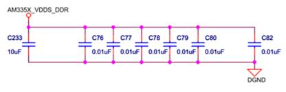
    It specifies that CVDDS_DDR is 10.06uF :

   And the capacitance on AM3358EVM is below (it is match the spec of Table 3-13):

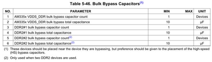
b) On the other hand, there is description about DDR2(sprs717e: P160).
    It specifies that the total capacitance on VDDS_DDR is 10.6uF. (It is NOT 10.06uF.)


Which is correct, a) or b) ?


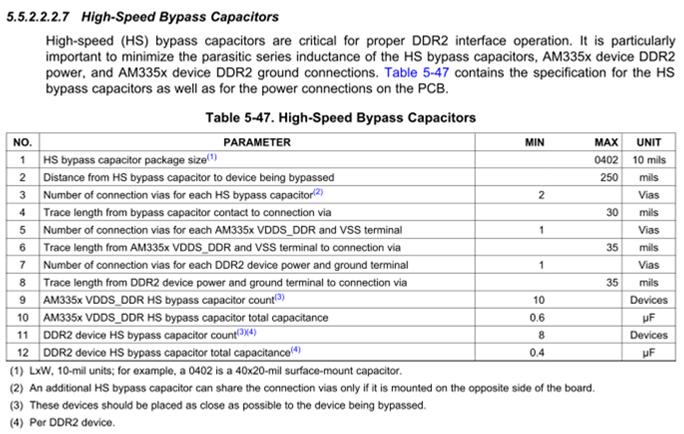
c) On table 5-47, the No.12 specifies that the total capacitance is 0.4uF.
    But, The capacitance on AM3358EVM is NOT 0.4uF. (It is total 0.08uF by 8 capacitors on EVM)
    Would you let me know the correct capacitance value?

Best regards, RY

  • Hi RY,
     
    Judging from reference designs Table 3-13 values (or rather Tables 5-46 and 5-47) are good for DDR2 designs, while Tables 5-60 and 5-61 are good for DDR3 designs. The datasheet guidelines should be followed when designing a new board.
  • Biser-san,

    I am very sorry.
    It was included some my mistakes above my question.
    So, I fixed the comments with lime green.

    Since I am gonna use the DDR2, your comment about DDR3 is no needed for our design.
    Can I understand that its DDR3 comment is just generally information?
    Or, are there any hints with related to design of DDR2 from your thinking?

    Our customer worries that whether my question can tell you enough. (It is my mistake, really sorry.)
    So, would you return below Yes/No question again?

    For DDR2 design:
     - Can I think that the appropriate total CVDDS_DDR capacitance is 10.06uF?
       (Its value is the EVM design)

     - Can I think that the DDR2 side appropriate total HS Bypass Capacitance is 0.08uF?
       (Its value is the EVM design)

    Best regards, RY

  • Hi RY,
     
    From AM335X Datasheet, Tables 5-46 and 5-47:
     
    AM335x VDDS_DDR: 1x10uF + 0.6uF (minimum 10 HS capacitors)
    For each DDR2 memory: 1x10uF + 0.4uF (minimum 8 HS capacitors)

  • Biser-san,

    Thank you so much for your quick response.

    Biser Gatchev-XID said:
    Judging from reference designs Table 3-13 values (or rather Tables 5-46 and 5-47) are good for DDR2 designs,


    From your answer, I thought that the Table 3-13 and EVM's capacitance is correct. (Table 5-46 and 5-47 is not correct.)
    Sorry, I am confusing.

    Do you prefer the capacitance of Table 5-46 and Table 5-47?

    Best regards, RY


  • Hi RY,
     
    In my opinion Table 5-46 and Table 5-47 should take precedence. I base this on Note (4) after Table 3-13.
  • Hello, Biser-san.

    Sorry for my late reply.

    Biser Gatchev-XID said:
    In my opinion Table 5-46 and Table 5-47 should take precedence. I base this on Note (4) after Table 3-13.

     
    I understand your thinking.
    But, it specifies TYP value of CVDDS_DDR in Table 3-13.
    I think that it is clearly different from what is described in Table 5-46 and Table 5-47.
    Because, it specifies MIN value in Table 5-46 and Table 5-47.
     
     - TYP 10.06uF (Table 3-13)
     - MIN 10.6 uF (Table 5-46 and Table 5-47)
    It is inconsistent.
    Could you check whether it is typo inside TI?
    Best regards, RY
  • We only specify the typical capacitance so customers have some flexibility in their system design.  It is much more important to optimize high-frequency capacitor placement and connections to AM335x power terminals than total capacitance.

    For example, the data sheet recommends a typical value of 10.08 uF for VDD_CORE, with a note describing how the 10.08 uF is a combination of one 10 uF bulk capacitor and eight high-frequency 10 nF capacitors.  The goal would be to place all of these capacitors as close as possible to the AM335x VDD_CORE terminals.  It is very important to place the high-frequency capacitors under the BGA area of the PCB to minimize inductance and loop area of their connections to the AM335x power terminals, but this is not as important for the bulk capacitors.  In most case there may not be enough room to place all eight of the high-frequency capacitors under the BGA without compromising the number of high-frequency capacitors connected to other power rails.

    The typical capacitor values recommended in the data sheet provide a starting point when beginning a product design.

    I will discuss the capacitor value differences shown in the data sheet with our IO expert and try to get you a better answer in a few days.

    Regards,
    Paul


  • Paul-san,

    Thank you very much for your information.
    Also I appreciate your strong support.

    I am waiting your feedback.

    Best regards, RY

  • Paul-san,

    I am sorry.
    I need the capacitor value by the evening of March 18th.
    Because, our important customer complete their schematic.
    I am waiting answer from you.

    I am very sorry and thank you in advance.
    Best regards, RY

  • We plan to remove the typical capacitance value and the reference to note (3) for the CVDDS_DDR parameter in Table 3-13  .  Note (4) will be used to reference the respective DDR section for capacitor recommendations.

    The capacitor recommendations in the respective DDR section are listed as minimums and not specific requirements.  For example, in Table 5-47 shows a minimum of 10 high frequency capacitors for AM335x VDDS_DDR with a minimum of 0.6uF capacitance.  In this case it would be best to use 10 - 0.1uF capacitors since 60nF capacitors are not a common value.

    As mentioned in my previous email, the number of capacitors used is not as important as the placement and low impedance connections of the capacitors.

    Regards,
    Paul

  • Paul-san,

    Thank you very much for your answer.

    I am very disappointing that the 10.06uF capacitance in Table 3-13 is not remain
    instead of the 10.6uF in Table 5-46 and Table 5-47 which is a larger capacitance is remain.

    The customer wants to proceed their design based on the EVM capacitance(10uF + 6x0.01uF)) and EVM placement.
    Because they would like to use small capacitance for board space.

    Can you accept this?

    If it is acceptable, they are going to develop according to the EVM design as their start point.
    And, when any trouble is occured, they will add the capacitor.
    They want to know whether it is acceptable or not.

    And, it is last day to complete their schematics today.
    Would you let me know your advice?

    Best regards, RY

  • I did not performed the analysis that derived the capacitor recommendations published in the data sheet.  Therefore, I can not provide any firm recommendation other than what is published in the respective DDR section of the data sheet. 

    If they must make a choice between placing larger capacitors around the BGA perimeter rather than placing the smaller capacitors under the BGA, I recommend they place as many small capacitors as possible under the BGA and also place the remaining large capacitors around the perimeter.  This seems like a reasonable compromise.

    Regards,
    Paul

  • Both 0.1uF and 0.01uF capacitors are freely available in sizes down to 0201.
  • Paul-san, Biser-san,

    Thanks a lot for your support!
    I am sorry for my late reply. I would like to report.

    They decided that they follow the datasheet description like below:
      DDR2 side:
       - 22uF x 1
       - 0.1uF x4
       - 0.001uF x 8

      AM335x side:
       - 10uF x 1
       - 0.1uF x 6
       - 0.001uF x 4

    The purpose of 0.001uF capacitor is for increasing the frequency characteristics.
    Because the impedance is the lowest when it operate 266MHz.

    If you have any considerations, would you let me know?

    Best regards, RY