This thread has been locked.

If you have a related question, please click the "Ask a related question" button in the top right corner. The newly created question will be automatically linked to this question.

How to get strong Noise immunity on AM335x VBUS line.

Guru 10570 points

Hello,

I am designing AM335x target board.
I am concerning how to get strong Noise immunity.

I have refered application notes(SPRAAR7: P1):
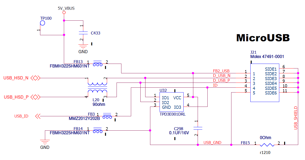
  Power going into and out of the cable: The USB connector socket pin 1 (VBUS ) may be heavily
  filtered and need only pass low frequency signals of less than ~100 KHz. The USB socket pin 4
  (analog ground) must be able to return the current during data transmission, and must be filtered
  sparingly.

Would you tell me advise?

To get strong Noise immunity on target board,
 - Are there any reference designs for Noize Immunity?
 - What kind of filter should I put on VBUS line?

Best regards, RY

  • Hi RY,
     
    In most cases 600Ohm ferrite beads are used on VBUS, along with 10-100nF capacitor. You will also need ESD protection, like TPD3E001DRL and probably a 90Ohm CMR filter on USB data lines. Here is an example:

  • Biser-san,

    Thanks for your support.
    We could see that USBx_VBUS terminal has broken in our some production boards.

    We think it is not sufficient ESD immunity in our board on USBx_VBUS line, and is regarding to characteristics of LC filter circuit.

    Question)
    For workaround, we are considering to change the design from LC filter circuit to RC filter circuit.
    Is it allowed? If you have any concern, please let me know.

    Our design) 
    R: 1Kohm
    C: 1uF

    Best regards, RY

  • The protection circuit U32 should be taking care of ESD events, however the RC circuit is OK if you want to implement it. I think 1uF is too much though, 100nF is what is used on our EVMs. Also if the 5V_VBUS voltage rail is used for anything else on the board, besides USB_VBUS sense pin, there will be voltage drop across the resistor that may interfere with proper functioning. Make sure you place the RC filter only on the line that connects directly to USB_VBUS sense pin, if anything else is supplied from VBUS, branch it before the RC filter.

  • 1 uF and 1KOhm will give you a time constant of 1ms. This is OK, because it's much less time than the human reaction time.

    The critical part of the ESD immunity is the maximum voltage across the resistor. You might use a high voltage resistor, or several small resistors in series.

    Do you have a pulldown resistor in parallel to the Capacitor? If not, how do you detect a disconnect of the USB cable?

  • The USB specification recommends USB peripherals to have a minimum VBUS capacitance of 1uF and a maximum VBUS capacitance of 10uF. I recommend you connect a 1uF capacitor directly to the VBUS pin of the Micro-B connector, insert a 1k ohm series resistor to the AM335x USBx_VBUS terminal, connect a 0.1uF capacitor to the other side of the series resistor and AM335 USBx_VBUS terminal.

    Regards,
    Paul
  • Everyone,
    Thanks for your advise.

    Paul-san,
    Your comment is final recommendation. Right?
    So, you recommend as follows. Is my understanding correct?

    Best regards, RY

  • Paul-san,
    Can I have your return regarding above confirmation?
    Best regards, RY
  • Paul-san,

    Hello,
    I have additional questions on this.

    - About your recommended circuit, is my understanding correct?

    - Does the AM335x VBUS terminal have Schmitt trigger circuits in it?

    - For our circuit does not have a discharge resistor, it will take some time to voltage drop after USB cable removal.
    Do you have any concern regarding to slowly to that the voltage to drop on the VBUS line?

    Best regards, RY

  • I'm sorry for the delayed reply. I was on vacation for the past few days.

    Your understanding is correct.

    I have reviewed the internal design specification and the VBUS comparator circuits do not appear to have any hysteresis. However, this should not be required because the VBUS capacitance will filter the signal and remove all high frequency transients. I would like to know why you are asking this question since this question is not related to the original topic of protecting the input from over-voltage transients. Hysteresis doesn't protect inputs from over-voltage transients.

    The internal PHY was designed to support OTG, so the VBUS terminal has an internal impedance of 40k - 100k ohms to ground as defined in the USB OTG specification.

    Regards,
    Paul
  • Paul-san,

    Thanks for your advise.
    I ask your question and have once more question.

    > I would like to know why you are asking this question since this question is not related to the original topic of protecting the input from over-voltage transients. Hysteresis doesn't protect inputs from over-voltage transients.

    Because I assume the destruction by the input of intermediate voltage, rather than overvoltage.
    Since there is no hysterisis in the VBUS comparator,does the Flow-through current be causing damage?
    e.g.) In the case Input voltage is same as VBUS threshold voltage.

    Best regards, RY

  • Applying intermediate voltage should not cause a problem.  The VBUS input is connected to a comparator circuit, not a digital input buffer.

    Regards,
    Paul