This thread has been locked.

If you have a related question, please click the "Ask a related question" button in the top right corner. The newly created question will be automatically linked to this question.

I2C and SPI Conflicts

Expert 2370 points
Other Parts Discussed in Thread: OMAP-L138

Hi,

I have been trying to merge BSL based UPP code and RTFS based MMCSD code to collect sample and store data in SD card, respectively for a long time but no success. Both examples are working independently but when I merge them they don't work. I checked the PINMUX for both the project, none of them use PIXMUX5 but when I combine them I noticed PINMUX5 has used which might be a problem but I am not sure.

According to Pix Multiplex Utility, there are PIN overlaps when SPI1 and I2C0 are used together. If this is the problem, how this problem can be solved to merge two projects ? If PIXMUX is not the problem, what other problem it could be or how to solve that ?

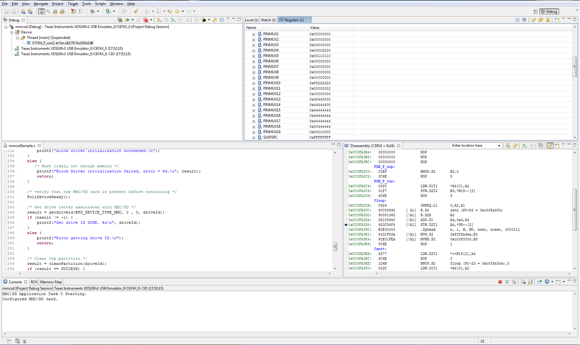
I attach snapshot, you can see that the code doesn't execute further then I halted the processor. PINMUX configurations are also visible. 

I appreciate your quick help.

Thanks.

BAS

  • Hi,

    Can anyone please reply ? I am in hurry to get my project done.

    Thanks.

    BAS

  • Anyone out there ?

  • Hi BAS,

    If there conflicts in the Pin Mux Utility, then you cannot use those peripherals together. I would suggest looking into porting your code to use an SPI and I2C that do not conflict.

    Thanks,

    Clinton

  • Hi,

    I am not sure if PINMUX is the real problem. I would really appreciate if you first confirm that uPP and RTFS based MMCSD code can't work together. I have not much idea about OMAP-L138 or how to do the porting thing. Can you please give me head start ?

    Thanks.

    BAS

  • According to PINMUX Utility, SPI1 can't be used with either of I2C ports. BSL based code (part of which given below) supplied by LogicPD does use I2C port to communicate with uPP.

    USTIMER_init();
    I2C_init(I2C0, I2C_CLK_400K);
    I2CGPIO_init(0x20);

    uPP is being used to collect data from A/D converter attached with UI board of the EVM. What do I do in this case ?

    I appreciate your sincere help.

    Thanks.

    BAS

  • Not quite sure about the SPI1 and I2C pinmux conflict. Some of the upper SPI1 CS lines conflict with I2C. Any reason you can't use one of the lower SPI1 CS lines instead? Have you checked to see if the two projects use the same interrupt numbers?

  • Norman,

    Thanks for your help.

    I checked the interrupt number, they are different.

    While debugging the code, I am unable to see where SPI1 are being active, as soon as it starts executing the EDMA code, I am unable to use breakpoint so I don't know how could I use lower SPI1 CS lines ?

    I appreciate if you have any input for my problem.

    BAS

  • From what I can tell from your screen capture, the I2C and SPI1 should not conflict. Assumes that SPI1 uses CS[0].

    PINMUX4 = 0x00002200
    Tri-stated selected instead ofSPI1_SCS[2]
    Tri-stated selected instead ofSPI1_SCS[3]
    Tri-stated selected instead ofSPI1_SCS[4]
    Tri-stated selected instead ofSPI1_SCS[5]
    I2C0_SDA selected instead of SPI1_SCS[6]
    I2C0_SCL selected instead of SPI1_SCS[7]

    PINMUX5 = 0x00110110
    SPI1_SIMO selected
    SPI1_SOMI selected
    Tri-stated selected instead of SPI1_ENA
    SPI1_CLK selected
    SPI1_SCS[0] selected
    TM64P2_IN12 selected instead of SPI1_SCS[1]

    The CS that SPI1 uses in specified in the registers SPIPC0.SCS0FUN[n] SPIDAT1.CSNR[n].

    I doubt that the PINMUX or SPI1 CS settings are the problem. I think you should look deeper in the interrupts. I vaguely remember on the DSP side, there is an IRQ for SPI and I2C. EDMA uses 2 IRQs. I think EDMA has channel allocations that might overlap. Maybe try using non-EDMA code first. I don't have a LogicPD board so I cannot say about the BSL code.

  • Norman,

    Thanks. I will again have a deeper look.

    There are codes without DMA but they don't support file system so RTFS based code which uses EDMA is the only option. But I will do more debugging and get back to you.

    Thanks a lot.

    BAS

  • Norman,

    I thoroughly went through the code and didn't find any channel allocation problem. I have found the function which doesn't execute completely, I mean it doesn't come back from the function given below and kept running somewhere. I think this is the line creating problem when I merge two projects.

    if (TRUE != SEM_pend(gMmcsdCallbackSem, SYS_FOREVER))
    {
    MMCSD_ERR_DEBUG(("\r\n MMCSD: Sem gMmcsdCallbackSem "
    "Take failed"));
    }

    if (gMmcsdDetectError != 0)
    {
    MMCSD_DRV_DEBUG(("\r\n MMCSD: Card init. failed"));
    result = gMmcsdDetectError;

    blkEventInfo.EventId = PSP_BLK_EVT_MEDREM;
    blkEventInfo.EvtData = \
    &gMmcsdDdaObj[instanceId].blkDrvInfo;

    Condition written in bold is the line which doesn't execute after merging the project. When I don't merge projects, condition in bold executes and pointer comes back to the next condition given without bold.

    Do you have any idea what's going on ?

    Thanks.

    BAS

  • I take it SEM_pend() is a BIOS function? I have little experience with BIOS. I'll state the obvious. I would guess that you need to trace how and where the semaphore gMmcsdCallbackSem is acquired and released. Maybe one project overwrites the other projects handler which releases the semaphore. That's all I got. Hopefully someone more knowledgable can help you.

  • Thanks Norman. 

    I don't know either what to do.

    Do you know any other way to have big memory to save large amount of data using OMAP-L138 EVM ?

  • I'm not familiar with the features of the OMAP-L138 EVM. I suppose you could try TFTP across ethernet. Good odds that a TFTP Ethernet project would also conflict with your uPP project. Can't think of anything else. Sorry.