This thread has been locked.

If you have a related question, please click the "Ask a related question" button in the top right corner. The newly created question will be automatically linked to this question.

Error while connecting TMS320C6745 Target

Other Parts Discussed in Thread: TMS320C6745, OMAP-L137

Hi,

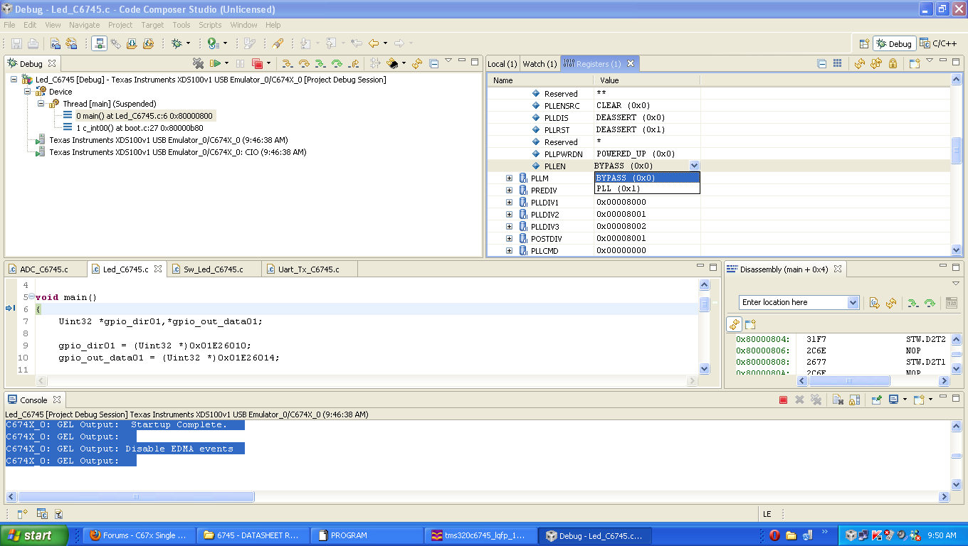
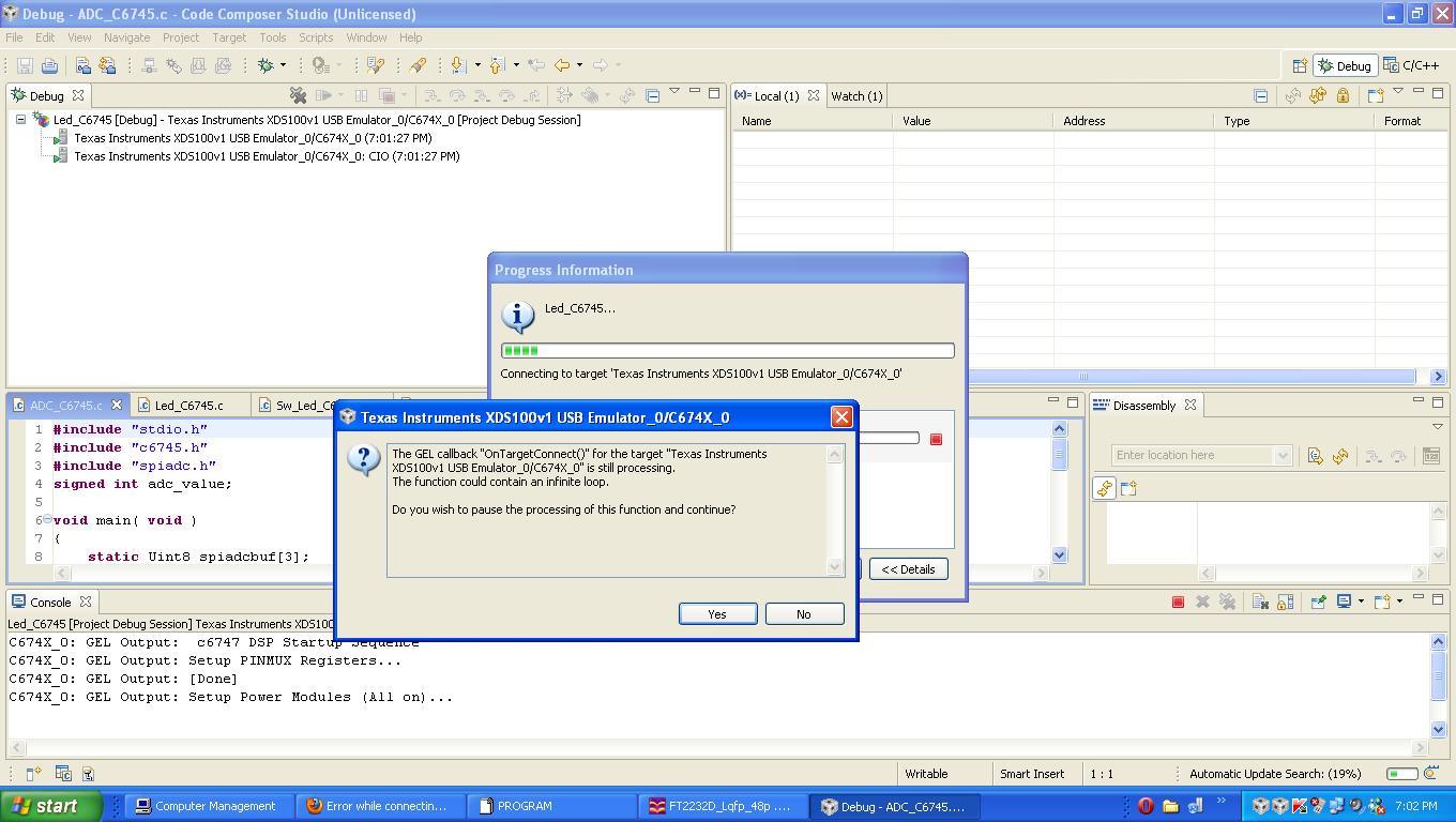
   Am using tms320c6745 kit with xds 100 usb emulator . am using code composer studio v4 . when i debug my project am getting the following error . what would be the problem ? , how to solve this ? please help soon................

Error:

Trouble Writing Memory Block at 0x1c10120 on Page 0 of Length 0x4:
Error 0x00000002/-1060
Error during: Memory,
An unknown error prevented the emulator from accessing the processor
in a timely fashion.
It is recommended to RESET EMULATOR.  This will disconnect each
target from the emulator.  The targets should then be power cycled
or hard reset followed by an emureset and reconnect to each target.

Many Thanks,

Thiyagarajan.S

  • hi,

      MORE INFORMATION TO SOLVE MY PROBLEM................

    When Am connecting the target , the above post message display in error box.

    the following error displaying are displaying at console window .............

    C674X_0: GEL Output:  c6747 DSP Startup Sequence  
    C674X_0: GEL Output: Setup PINMUX Registers...
    C674X_0: GEL Output: [Done]
    C674X_0: Trouble Writing Memory Block at 0x1c14038 on Page 0 of Length 0x4: Error 0x00000002/-1178 Error during: Memory,  The target does not have a CPU clock.   
    C674X_0: GEL: Error while executing OnTargetConnect(): target access failed.
    C674X_0: Trouble Reading Register CSR: Error 0x00000004/-1178 Error during: Register,  The target does not have a CPU clock.   
    C674X_0: GEL Output:  
    C674X_0: Trouble Halting Target CPU: Error 0x00000020/-1178 Error during: Execution,  The target does not have a CPU clock.   

    Many Thanks,

    Thiyagarajan.S

  • Thiyagarajan,

    Before trying to connect to the target, remove the GEL file so it will not be executed. Once you have connected to the target DSP, try looking at the registers in the SYSCFG module and in the PSC0 module to see if you can access those and if their values match what the datasheet says the default values should be.

    Perhaps your Target Configuration is not built for the correct version of the XDS100? There are v1, v2, and v3, but I do not know how they would behave if configured for the wrong one.

    If you are using a EVM board, there should not be hardware design or manufacturing problems, but you may have to start looking at input and outputs for clocks and reset to see if everything is working correctly.

    Regards,
    RandyP

  • Hi RandyP,

        Thanks a lot for replying me.

        I configured the target file correctly am using xds100 usb v1 emulator only. its our own development kit. am suspecting the problem at PLL locking , i think that my pll was not locking . Is their any testing to check about pll locking  ?

    Many Thanks,

    Thiyagarajan.S

  • Hi RandyP,

                    Am using CCS version 4 , my target is TMS320C6745, connecting Device type : XDS100 USB emulator version 1 .

    without that gel file my kit connecting with the software. then how can i proceed to solve my error. Please Kindly Help me Sir.

    here I attached my gel file for your reference .

    3073.evmc6747_dsp.gel

    My Target IC Name ( The following as displaying in TMS320C6745 IC):

    TMS320

    C6745CPTP3

    YF-28AF8VW G4

    21 538 PTP

    Many Thanks,

    Thiyagarajan.S

  • Thiyagarajan,

    Thiyagarajan . S said:
    without that gel file my kit connecting with the software. then how can i proceed to solve my error.

    When I have had a problem like this, I will try

    1. Edit the GEL file to only do a few steps to find out where the problem comes from within the GEL file.

    2. Try operations that are failing by manually testing them in CCS, such as reading or writing a register from the Expressions or Memory Browser windows.

    Once you find the exact part of the GEL file that is causing the problem, you will have to figure out whether the GEL file is wrong or if there is a problem in your board. Some of the board problems to look for are

    a. Power supply level or power supply sequencing problems. Refer to the datasheet and Hardware Design Guide for more information.

    b. Clocks and resets need to match the requirements for the power-on sequencing.

    c. All boot-strap pins used for device configuration must have the correct pull-up or pull-down resistors, when needed.

    Regards,
    RandyP

  • RandyP,

    1.              i dont know ,, how to omit the lines in gel file. in gel all the lines important . is it possible to run a gel file using  breakpoints if yes tell me  how to run a gel with manually.

    2.  kindly tell me how to check the following things in our board. :

    a. Power supply level or power supply sequencing problems. Refer to the datasheet and Hardware Design Guide for more information.

    b. Clocks and resets need to match the requirements for the power-on sequencing.

    c. All boot-strap pins used for device configuration must have the correct pull-up or pull-down resistors, when needed.

    3. in my hardware cpu reset is available , but its not working . if we give an reset low signal what would the output, how you known that processor has resetteed. Is their any testing methods to test the reset out.or processor will response for reset signal . ?

    4. totally we bought  20 new TMS320C6745 new IC . is their any problem with device? from this two of the processor are working with same gel file.

    5. at sometimes it enters the debug window, at that time i checked it . PLLCTL register PLLEN was bypass, but as per the gel file the PL LEN bit was wrote as 1. it always read as one. what would be the reason for this issue.?

    Sir, Kindly give some solution to our problem. we waiting.....

    Many thanks

    Thiyagarajan.S

  • Thiyagarajan,

    Thiyagarajan . S said:
    1.              i dont know ,, how to omit the lines in gel file. in gel all the lines important . is it possible to run a gel file using  breakpoints if yes tell me  how to run a gel with manually.

    To omit lines, you can either comment them out or delete the lines. Be sure to keep a copy of the original file for later use. You cannot use DSP breakpoints to stop inside a GEL file.

    Thiyagarajan . S said:

    2.  kindly tell me how to check the following things in our board. :

    a. Power supply level or power supply sequencing problems. Refer to the datasheet and Hardware Design Guide for more information.

    b. Clocks and resets need to match the requirements for the power-on sequencing.

    c. All boot-strap pins used for device configuration must have the correct pull-up or pull-down resistors, when needed.

    This sounds like a very basic question. You should consider contacting one of the TI Design Network companies that are knowledgeable on issues of board design and development. There should be one or more companies available with experience with this DSP who can help you to test your board and figure out what the problems may be, and how to redesign the board once those problems are known.

    You use voltmeters and oscilloscopes to check signals and waveforms. If you do not have this equipment or do not have experience with using them, you will want to make other arrangements for debugging your board.

    Thiyagarajan . S said:
    3. in my hardware cpu reset is available , but its not working . if we give an reset low signal what would the output, how you known that processor has resetteed. Is their any testing methods to test the reset out.or processor will response for reset signal . ?

    Please see the datasheet and the section on Reset to understand the direct signalling effects and the reset effects.

    Thiyagarajan . S said:
    4. totally we bought  20 new TMS320C6745 new IC . is their any problem with device? from this two of the processor are working with same gel file.

    There should be no problems with the devices that were delivered to you from an Authorized TI Distributor. How many of the processors are failing?

    Regards,
    RandyP

  • RandyP,

                Sir you not answered for fifth question in my previous post about pll.

    Here i attached my error window snapshot image.

    In that PLLCTL  register, PLLEN  always it as bypass mode, if i changed manually to PLL it nos changing. what is the reason ?, at sometimes my gel file running at the end only problem has arising. the following error is running in console window while debug:

    C674X_0: GEL Output:  c6747 DSP Startup Sequence  
    C674X_0: GEL Output: Setup PINMUX Registers...
    C674X_0: GEL Output: [Done]
    C674X_0: GEL Output: PLL Setup Complete
    C674X_0: GEL Output: Setup Power Modules (All on)...
    C674X_0: GEL Output: [Done1]
    C674X_0: GEL Output: [Done2]
    C674X_0: GEL Output: [Done3]
    C674X_0: GEL Output: [Done4]
    C674X_0: GEL Output: [Done5]
    C674X_0: GEL Output: [Done6]
    C674X_0: GEL Output: [Selva Commented PSC0_lPSC_enable(0, 6); ]
    C674X_0: GEL Output: [Done8]
    C674X_0: GEL Output: [Done9]
    C674X_0: GEL Output: [Done10]
    C674X_0: GEL Output: [Done11]
    C674X_0: GEL Output: [Done12]
    C674X_0: GEL Output: [Done13]
    C674X_0: Trouble Reading Memory Block at 0x1e27a14 on Page 0 of Length 0x4: Error 0x00001002/-1137 Error during: Memory, Target,   It appears that the target is being held in reset.  This may be due to Wait-In-Reset (WIR) configuration set by the EMU0=0 and EMU1=1 pin settings.  If this is the case, DISCONNECT all CONNECTED devices including icepick and then select RETRY to clear the WIR configuration.  If this is a multi-core system, the master CPU may not be releasing the DSP/MCU from reset.  Please check your configuration in CC_setup and/or your GEL file to ensure that nothing is blocking the DSP/MCU from being released from reset  
    C674X_0: GEL Output: [Done]
    C674X_0: GEL Output: SDRAM Setup Complete
    C674X_0: GEL Output:  Startup Complete.  
    C674X_0: GEL Output:  
    C674X_0: GEL Output: Disable EDMA events
    C674X_0: GEL Output:  
    C674X_0: Trouble Reading Memory Block at 0x1c1111c on Page 0 of Length 0x4: Error 0x00001022/-1176 Error during: Memory, Execution, Target,  The IM memory request is not serviced by the HW memory system.  This could be caused by the memory address specified does not exist in the specified  memory/cache level.   
    C674X_0: Power Failure on Target CPU: Error 0x00000020/-2011 Error during: Execution,  An internal error occurred in which an illegal action (0x0000004B) was requested while disconnected.  
    C674X_0: Failed to remove the debug state from the target before disconnecting.  There may still be breakpoint op-codes embedded in program memory.  It is recommended that you reset the emulator before you connect and reload your program before you continue debugging

     Again  am attaching my gel file for your reference.

    5141.evmc6747_dsp.gel

    why pll is not enabling in my device ? what may be the reason ?

    Many Thanks,

    Thiyagarajan.S

  • Randyp,

               At the same board am getting different error for each trying , the error i received few are listed the below ,

    1. While running gel file it hangs after the enter of PSC on loop, and it showing as error :

    The GEL callback "OnTargetConnect()" for the target "Texas Instruments XDS100v1 USB Emulator_0/C674X_0" is still processing.
    The function could contain an infinite loop.

    Do you wish to pause the processing of this function and continue?

    then i proceed with yes, it enter into debug but  at this i cant able to write even cpu register .

    2.  While running gel file it hangs after the enter of PSC on loop, and it showing as error :

    Error connecting to the target:
    Error 0x80000240/-1146
    Fatal Error during: Initialization, OCS,
    Invalid data was scanned by the emulation controller.
    Verify the board setup to make sure the scan chain is properly
    defined.
    If the setup is correct, then RESET EMULATOR.  This will disconnect each
    target from the emulator.  The targets should then be power cycled
    or hard reset followed by an emureset and reconnect to each target.

    3.  if i attempt to debug , then it show a following a error:

    Error connecting to the target:
    Error 0x80000240/-1180
    Fatal Error during: Initialization, OCS,
    The target is stuck in Wait-in-Reset mode.  The applied reset must be released before progressing.

    Expecting your help soon......

    Many Thanks,

    Thiyagarajan.S

  • Thiyagarajan,

    It will be difficult to provide you with better answers. It appears that you have a hardware problem of some type, and you are doing some of the right things to find it. If you have another board to try these tests on, please do that so you can confirm if it is a board manufacturing problem or a board design problem.

    What board design did you start from to generate your kit's design? You can look at the changes you made to provide a starting list of problems that may have been caused.

    In your post with the CCS screenshot, your GEL file is showing some debug prints such as [Done13]. That seems to be the point where the problem comes up. What is the GEL file doing after printing [Done13]?

    In your post above, once the error in step 1 happens, it appears that the emulator cannot get control of the DSP. You probably have to do a Disconnect Target command in CCS and then power cycle your board or do a hard reset before you will be able to try debugging again.

    These problems appear to be hardware problems with your board and not software problems that can be solved by changing a register setting. Continuing to debug into the GEL file will help you determine exactly which thing is being initialized when the errors show up, and then you will be able to direct your hardware testing with that knowledge.

    In my second post on this thread, I listed some general suggestions for what to look at on your board:

    RandyP said:
    Once you find the exact part of the GEL file that is causing the problem, you will have to figure out whether the GEL file is wrong or if there is a problem in your board. Some of the board problems to look for are

       a. Power supply level or power supply sequencing problems. Refer to the datasheet and Hardware Design Guide for more information.

       b. Clocks and resets need to match the requirements for the power-on sequencing.

       c. All boot-strap pins used for device configuration must have the correct pull-up or pull-down resistors, when needed.

    I am sorry that I cannot be more specific, but this will require your engineering and testing skills and test equipment to validate your board design and to find the problem. The GEL debug may help to narrow the search.

    Regards,
    RandyP

  • RandyP,

    1.

    In your post with the CCS screenshot, your GEL file is showing some debug prints such as [Done13]. That seems to be the point where the problem comes up. What is the GEL file doing after printing [Done13]?

    after that Done13., as per gel file it power up the PSC1 all modules..............

    2.

    In that PLLCTL  register, PLLEN  always it as bypass mode, if i changed manually to PLL it nos changing.  why pll is not enabling in my device ? what may be the reason ?

    3.

    I have C6745 custom board previously we have used TMS320C6745BPTP3. It was worked fine. but now again we assemble 20 kits with newly came ic ,, which name is TMS320C6745CPTP3. what is the difference between these two ic ?, I suggest my problem is in PLL . it not enabling, for what reason it stuck enabling ? or else anything i need to extra care for C revision. ?

    Sir, as last Kindly reply for this three question............... please ?

    Many Thanks,

    Thiyagarajan.S

  • Thiryagarajan,

    You have posted this question directly on the post at http://e2e.ti.com/support/dsp/tms320c6000_high_performance_dsps/f/115/t/253168.aspx so I will let someone answer there. I do not know the differences.

    You are doing a good job at debugging. Please continue to find the details of the problem such as when it happens in the GEL file.

    Usually, there are no problems like this when moving from one revision to the next. We will see what comments come to you on the other thread.

    Regards,
    RandyP

  • RandyP,

              Sir, i really thank t your continue post with me.  Finally i uninstalled my Code Composer Studio then re installed the software. Now my few of the kits are working fine. it mean that C revision is not a issue for my problem.

    1. But yet am struggling with 6 more kits. in that 6 kits, Voltage ok, Reset ok, Clock also ok. but it's not working. the same type of error it displaying . What would be the problem ?.

    2. And four more kit SDRAM are not working, at whole sdram space it displaying a some default constant. At every power up this constant is varying. i cant able to write values in sdram location. 

    Many Thanks,

    Thiyagarajan.S

  • Thiyagarajan,

    Thiyagarajan . S said:
    1. But yet am struggling with 6 more kits. in that 6 kits, Voltage ok, Reset ok, Clock also ok. but it's not working. the same type of error it displaying . What would be the problem ?.

    You have a lot of different error messages in this thread, so "the same type of error" is not clear. All of the suggestions and advice above still apply as you continue to work on these problems. I am very surprised that re-installing CCS made a difference, unless it was a way to get the latest emulation drivers. Be sure to do an Update from the Help menu after your installation; this will make sure the latest drivers will be pulled in.

    Otherwise, you can continue debugging and offer any specific details you learn as you debug into the GEL file and check related pins.

    Thiyagarajan . S said:
    2. And four more kit SDRAM are not working, at whole sdram space it displaying a some default constant. At every power up this constant is varying. i cant able to write values in sdram location. 

    If you are lucky, this will give you some good hints about manufacturing problems that may point you to solutions for your other kits, too. You can easily write specific tests to exercise the SDRAM interface pins and watch the activity on those pins.

    You could try replacing the SDRAM chips and see if they work beffer. Or you could try replacing the DSP chips, although that tends to be more difficult and expensive, so it is usually the last thing to try.

    Regards,
    RandyP

  • Randyp,

                Sir, one of my 6745 custom board reset is always low(1v). At power up reset (RST#) is 3V then gradually it start decreasing to 1v within a second . for what reason the processor will behave like this ?

    For your reference i attached the Reset Schematic here.

    Am expecting the reply..............

    Many Thanks,

    Thiyagarajan.S

  • Thiyagarajan,

    Thiyagarajan . S said:
    At power up reset (RST#) is 3V then gradually it start decreasing to 1v within a second . for what reason the processor will behave like this ?

    The C6745 will not directly behave like this, or it would never be able to function. The C6745 RESETn pin does not have a huge capacitor with a huge resistor to bleed it to ground.

    Something is causing this behavior other than the normal behavior of the C6745. Do you have an EVM or development board that you can compare the signals with?

    How many boards have you built? Do you have others that show this same behavior?

    Regards,
    RandyP

  • Randyp,

                Sir,  i have five more board , which is not working on board xds100 usb emulator. but now i have a external xds100 usb version 1 emulator. if i connect external emulator  with board, it starts running but stuck while running gel  file, and show some error >

    Error:

    C674X_0: GEL Output:  c6747 DSP Startup Sequence  
    C674X_0: GEL Output: Setup PINMUX Registers...
    C674X_0: GEL Output: [Done]
    C674X_0: Trouble Writing Memory Block at 0x1c14038 on Page 0 of Length 0x4: Error 0x00000002/-1178 Error during: Memory,  The target does not have a CPU clock.   
    C674X_0: GEL: Error while executing OnTargetConnect(): target access failed.
    C674X_0: Trouble Reading Register CSR: Error 0x00000004/-1178 Error during: Register,  The target does not have a CPU clock.   
    C674X_0: GEL Output:  
    C674X_0: Trouble Halting Target CPU: Error 0x00000020/-1178 Error during: Execution,  The target does not have a CPU clock.   

    for what kind of reason this error may occur in ccs:  sir, kindly discuss with ccs expert people (for what  this error will display)and reply soon .

    i want to finish this work as soon.

    Many Thanks,

    Thiyagarajan.S

  • Thiyagarajan,

    Since you have 6 custom boards that all have similar problems, you either have a serious design problem with the board or a serious manufacturing problem with the board.

    If you have not done so already, please refer to the Hardware Design Guide for your device for additional information and suggestions for debug. You can find this on the TI Wiki Pages by searching for "c6747 hardware design guide" (no quotes). It may be listed under the OMAP-L137 name, which will also apply. There is also a Getting Started Guide there that may be of help, but the Hardware Design Guide will be a good resource for you to follow.

    There are companies on our TI Design Network who can review your schematics and layout databases to suggest problems with the design. You will want to consider this. Your alternative is to go through the design signal-by-signal and review every detail of the datasheet and the errata and any documentation from the TI.com TMS320C6745 Product Folder page that is related to each signal.

    There are also companies on our TI Design Network who can help you with board debug from their prior experience. This would need to be done in person or for you to ship your board to them. Your alternative is to look carefully at every signal and pin on the board to see how it is behaving electrically and logicly. This includes using the proper test equipment to avoid affecting the board during testing, such as high-impedance probes and high-frequency equipment. This includes looking at the signal levels and noise levels on all the signals and power lines.

    At one point you said "Voltage ok, Reset ok, Clock also ok.", and then later you found that the reset line was not okay. This is critical to getting your board operating, and sufficient to require a solution before moving to any other problem on your board.

    Power sequencing is also critical. This must be observed using multi-trace test equipment to make sure you are powering the board correctly, not by measuring the voltage using a Volt meter.

    The documents referenced above and all the suggestions in this thread may offer some help. Please keep us posted on your progress.

    Regards,
    RandyP

  • RandyP,

        " There are also companies on our TI Design Network who can help you with board debug from their prior experience. This would need to be done in person or for you to ship your board to them.  "

    i dont know about such companies. am in india (Tamil Nadu State) , Kindly provide such contact to me, so that i approach them immediately.

    Many Thanks,

    Thiyagarajan.S

  • Thiyagarajan,

    Please go to TI.com and click on the Support & Community tab. You will see a link there for TI Design Network. Click on that link to get a page where you can put in your support needs. You can put in the Country as India, but I am not sure you can put in Tami Nadu State. But you will be able to determine from the available companies which ones may have an office near you.

    Try several different Engineering Services types, since there is not one that says Board Debug. I think many of our EVM and development board vendors are in India, and some of them may also provide engineering services.

    Regards,
    RandyP

  • Thiyagarajan.S,

    Can you please give an updated status of where you're at with things:

    • How many total boards do you have?
    • How many are having issues?
    • Is there any correlation to silicon rev?
    • Are you still seeing weird behavior around the reset pin?
    • Do the CCS error messages only happen after you lock the PLL?
    • If you're comfortable posting some snippets of your schematic showing the JTAG connection (and perhaps clocking and reset too) then I would have a quick look.

    Brad

  • Brad,

          Thanks for your kind reply and helping me, total 11 boards i have. I separated the group of kits by error wise. First we try to solve a simple thing errors. 

    For, Five boards i programmed XDS 100 USB EMULATOR V1 eeprom, it successfully get detected in device manager.  confirmation image for your reference.

    then usually i start led project work with code composer studio to test the assembled led in board. ( this is my first testing peripheral )

    then i press debug the active project. ( Dont confuse with project and source code whether its working or not , it everything correct and perfect previously i was tested 100 more boards using this same project and source code).

    then it successfully launching debug session.

    then it started connecting the target.

    then it started running the gel file.

    at here only problem arises. while running gel file,

    1. Displaying the some error 

    2. hangs at same where.

    1. Error Message:

    C674X_0: GEL Output:  c6747 DSP Startup Sequence  
    C674X_0: GEL Output: Setup PINMUX Registers...
    C674X_0: GEL Output: [Done]
    C674X_0: Trouble Writing Memory Block at 0x1c14038 on Page 0 of Length 0x4: Error 0x00000002/-1178 Error during: Memory,  The target does not have a CPU clock.   
    C674X_0: GEL: Error while executing OnTargetConnect(): target access failed.
    C674X_0: Trouble Reading Register CSR: Error 0x00000004/-1178 Error during: Register,  The target does not have a CPU clock.   
    C674X_0: GEL Output:  
    C674X_0: Trouble Halting Target CPU: Error 0x00000020/-1178 Error during: Execution,  The target does not have a CPU clock.  

    2. Hangs at some where (Usually after that gelout("Done 13")):

    C674X_0: GEL Output:  c6747 DSP Startup Sequence  
    C674X_0: GEL Output: Setup PINMUX Registers...
    C674X_0: GEL Output: [Done]
    C674X_0: GEL Output: PLL Setup Complete
    C674X_0: GEL Output: Setup Power Modules (All on)...
    C674X_0: GEL Output: [Done1]
    C674X_0: GEL Output: [Done2]
    C674X_0: GEL Output: [Done3]
    C674X_0: GEL Output: [Done4]
    C674X_0: GEL Output: [Done5]
    C674X_0: GEL Output: [Done6]
    C674X_0: GEL Output: [Selva Commented PSC0_lPSC_enable(0, 6); ]
    C674X_0: GEL Output: [Done8]
    C674X_0: GEL Output: [Done9]
    C674X_0: GEL Output: [Done10]
    C674X_0: GEL Output: [Done11]
    C674X_0: GEL Output: [Done12]
    C674X_0: GEL Output: [Done13]

    after coming to this place. it keeps on connecting,  nothing is happen,, that prict screen image is i added for your reference,.

    Sir, kindly Please first give a solution for this two issues., we will move one by one.

    Here i attached my gel file for you reference.

    4807.evmc6747_dsp.gel

    Many Thanks,

    Thiyagarajan.S

  • Can you simplify things further?  For example, please temporarily remove the section that does PLL initialization as well as EMIFA/EMIFB initialization.  See if you can run a "blink LED" program from internal memory.

  • Brad,

        i just comment the thing as you said.

    OnTargetConnect( )
    {
        GEL_TextOut( "\nc6747 DSP Startup Sequence\n\n" );

        Setup_Data_Cache();             // Setup L1D to 32 KB cache

        Setup_System_Config( );         // Setup Pin Mux and other system module registers
        //Setup_PLL();                    // Setup PLL0 (300MHz DSP, 133MHz EMIFs)

        Setup_Psc_All_On( );            // Setup All Power Domains

       // Setup_EMIFA();                  // Async EMIF
       // Setup_EMIFB();                  // Setup SDRAM

        GEL_TextOut( "\nStartup Complete.\n\n" );
    }

    when i start debug,  while connecting it start running gel file .

    C674X_0: GEL Output:  c6747 DSP Startup Sequence  
    C674X_0: GEL Output: Setup PINMUX Registers...
    C674X_0: GEL Output: [Done]
    C674X_0: GEL Output: PLL Setup Complete
    C674X_0: GEL Output: Setup Power Modules (All on)...

    after this , it keeps on connecting

    after some seconds ,it displaying as follow.

    if i give yes to continue, it look like below image, here i cant able to use run operation. only i can able to do operate halt or terminate all.

    these are the things i got ......

    Waiting for your to debug

    Many Thanks,

    Thiyagarajan.

  • Comment out Setup_Psc_All_On().  I expect that it should connect cleanly at that point.  Next you'll need to determine which specific modules in Setup_Psc_All_On() are causing you issues.  You'll need to selectively comment out modules to determine which ones are problematic.  I would probably do a binary search just to make things quicker, e.g. try only the first half, then try only the second half, etc.

  • Hi,

        Thanks to you both my most of the board was worked , the problem is i got less oscillator  voltage, after tuned then i got 150mv 24mhz . now the processors are working and behaving good. ( This is a Solution point for other engineers who facing same problem).

    my last  six more board i cant able to solve it, i need some ideas from you. these all six boards only problems in 1.2v and reset. Behavior notes for your understand :

    1. two boards 1.2v keep on increasing and oscillating to 1.2v to 1.7v

    2. two boards reset is always low.

    3. two more we have both the problem.

    Kindly help me in this ....................

    Many Thanks,

    Thiyagarajan.S

  • Your remaining issues sound like manufacturing problems.  I don't know that there's much more we can do on the forum to help you problem solve.  You might check a few things such as:

    • Use multimeter to measure the resistance from various power rails to ground.
    • Use mutlimeter to measure the resistance between various power rails
    • Perhaps reflow the board in case you have some bad solder joints, etc.

    I would expect you either have a bad connection somewhere, or perhaps a bad component (defective capacitor, etc.).