This thread has been locked.

If you have a related question, please click the "Ask a related question" button in the top right corner. The newly created question will be automatically linked to this question.

USB Host with USBHUB operation

Other Parts Discussed in Thread: AM3352, TPS2052, TPS2052B

I want to implement USB host ports using a USB Hub on a custom board I am designing using AM3352.  I am using USB2412 and TPS 2052.  

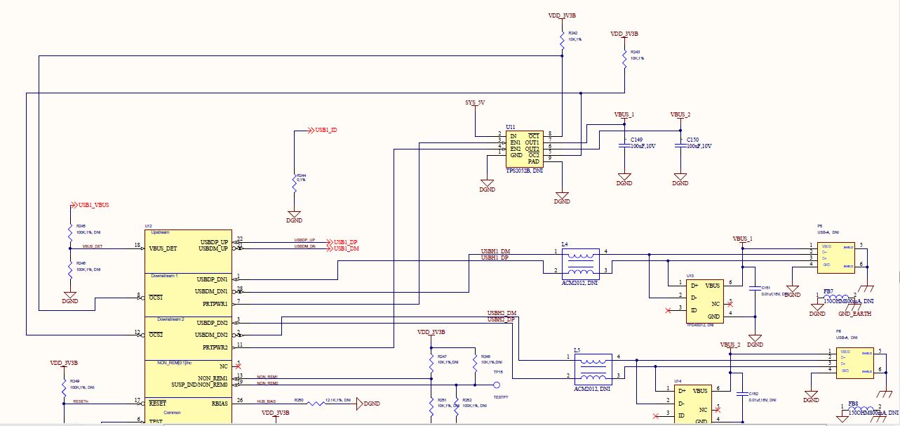
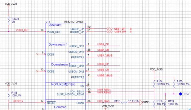
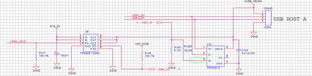
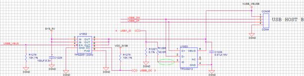
I have made almost all the connections for USB2412 as per its eval board and taking reference from Beaglebone.  Now for Host operation, USB_ID pin is grounded. USB_DP and USB_DM from processor are at upstream of usb hub and at downstream ports are two USB A connectors.  VBUS signals for  downstream ports has been provided from TPS2052. 

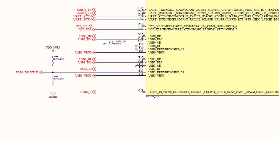
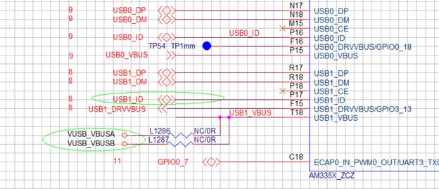
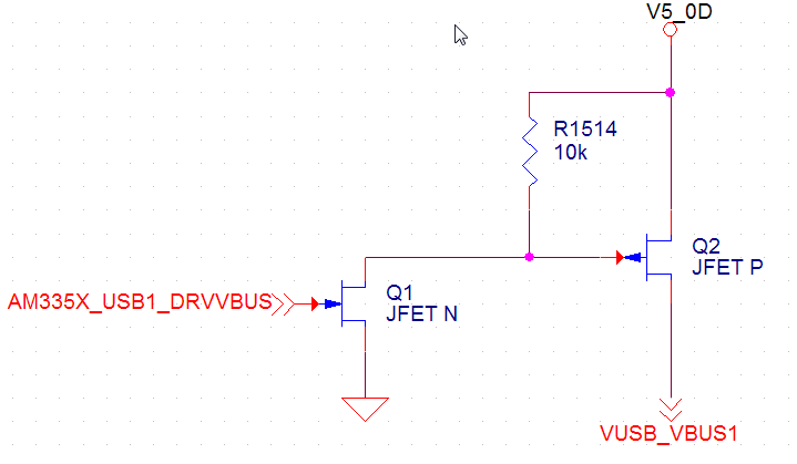
Now the problem that I am facing is how to configure or connect USB_DRVVBUS pin on processor ?? I cannot leave it NC because the schematics checklist that it should be connected to Enable of Power distribution switch. But, that Enable is already controlled by pins from respective downstream ports in USB HUB.  So How do i use USB_DRVVBUS , because it will control the USB_VBUS from processor, which I have used to enable the USB HUB itself.

 Pulling Up USB_DRVVBUS seems to be the only possible solution.  Please help me resolve this problem. 

  • Hi Nitesh,
     
    It would be helpful if you can post the section of your schematics with the connections between the AM335X and the USB2412.
  • Sir, 

    I have uploaded the relevant section of the schematics.


  • Hi Nitesh,
     
    The correct way to connect will be to add a 5V load switch, with power input connected to SYS_5V, power output connected to USB1_VBUS and control signal connected to USB1_DRVVBUS. Please note that USB1_VBUS is not a 5V source, it's a sense input.
     
    Another possible way to do this would be to drive an open-drain non-inverting buffer with busser input connected to USB1_DRVVBUS, and buffer output connected to USB1_VBUS and open-drain output pull-up resistor to SYS_5V.
  • Biser Sir,

    I have used TPS2052B  as 5V load switch, whose power input is connected to SYS_5V , power outputs to VBUS of the host connectors and control signal is provided by USB HUB.  

    Only thing I am concerned is that if I have made the USB port as Dedicated Host by grounding USB_ID port, do i need to involve USB_DRVVBUS and USB_VBUS on the glue IC side. Please put some light on that.

    I will consider the design with the open-drain non-inverting buffer with my senior though. 

  • Nitesh Singh said:

    Only thing I am concerned is that if I have made the USB port as Dedicated Host by grounding USB_ID port, do i need to involve USB_DRVVBUS and USB_VBUS on the glue IC side. Please put some light on that.

     
    Yes, by all means. The USB OTG peripheral in the AM335X has hardware dependency on these signals. In Host mode USB_DRVVBUS is driven after which a valid USB voltage is expected on the USB_VBUS input. If this isn't observed the USB will not work correctly. There is no software workaround for this requirement.
  • Hi Sir, 

    Just closing comments required for this issue, so as to make sure what I have understood is right.

    Refering to the text from section 16.3.1 from AM335X TRM : "

    When any of the USB controllers assumes the role of a host, the USB is required to supply a 5V power
    source to an attached device through its VBUS line. In order to achieve this task, the USB controller
    requires the use of an external power logic (or charge pump) capable of sourcing 5V power. A
    USB_DRVVBUS is used as a control signal to enable/disable this external power logic to either source or
    disable power on the VBUS line. The control on the USB_DRVVBUS is automatic and is handled by the
    USB controller. The control should be transparent to the user so long as the proper hardware connection
    and software initialization are in place. The USB controller drives the USB_DRVVBUS signal high when it
    assumes the role of a host while the controller is in session. When assuming the role of a device, the
    controller drives the USB_DRVVBUS signal low disabling the external charge pump/power logic; hence,
    no power is driven on the VBUS line (in this case, power is expected to be sourced by the external host).
    Note that both USBs are self-powered and the device does not rely on the voltage on the VBUS line
    sourced by an external host for controller operation when assuming the role of a device. The power on the
    VBUS is used to identify the presence of a Host. It is also used to power up the pull-up on the D+ line.
    The USB PHY would continually monitor the voltage on the VBUS and report the status to USB controller"


    It is almost clear that the Enable for the USB HUB is to be controlled by the USB1_DRVVBUS signal which will in turn drive the TPS2052 switch. When TPS2052 switch is on , either of the outputs will generate VBUS signal for the respective host connector. If this VBUS is connected to USB1_VBUS , which is a sensing input, it conveys to the USB controller that the switch is activated and 5V is connected to USB host connector. Now the USB1_DRVVBUS is signal is pulled high when the USB OTG port on the processor acts as host, which we have previously achieved by grounding the ID pin.  I have checked this configuration in alitum, no errors were generated for USB1_VBUS. 
    Only doubt is , is USB_DRVVBUS high at 3.3V or any other voltage, because the USB HUB needs 3.3V or higher to be enabled.
    At what voltage is USB_DRVVBUS high by the USB Controller on the processor ?? And connecting multiple VBUSx from TPS2052, as shared in figure in queries above, to USBx_VBUS is fine ??
  • Hi Nitesh,
     
    USBx_DRVVBUS I/O cells are powered from the VDDSHV6 domain, so active high level will be either 1.8V or 3.3V, depending on the VDDSHV6 power supply.
    As for connecting multiple VBUSx from TPS2052 to USBx_VBUS, I don't think this is a good idea. A better solution will be the one that can be seen on the Starter Kit schematic (http://processors.wiki.ti.com/images/a/a2/TMDSSK3358_3H0009_REV1_2B_SCH.pdf). Please check page 16, component U5B, which is used to signal the processor that VBUS is present. You could design something similar.
  • Biser Sir, 

    Why is connecting VBUSx from TPS2052 to USBx_VBUS a bad idea ?? I mean it should be working alright, as far as i can deduce from the circuit. 

    The solution that you have suggested, it is using a open drain buffer to generate VBUS signal at 5V from 3.3V PRTPWR signal from the USB HUB. I am already using this PRTPWR pin to enable TPS2052 as this was the suggested way in the evaluation schematics for USB2412 ( USB HUB).  (http://www.smsc.com/index.php?tid=295&pid=245)   .  

    Going by your suggestion , I add this extra buffer circuit to PRTPWR1 and PRTPWR2 , apart from connecting to EN1 and EN2 of TPS2052B , to  generate USBx_VBUS similar to the schematics you are refering to. 

  • Nitesh Singh said:

    Why is connecting VBUSx from TPS2052 to USBx_VBUS a bad idea ?? I mean it should be working alright, as far as i can deduce from the circuit. 

     
    You have two USB connectors. How are you going to connect both VBUS rails to one USBx_VBUS input? Direct connection won't do, because it will short the VBUS rails on the two connectors.
  • Sir, 

    Thank you sir for bringing that into notice. I did not consider that  condition. 

    So you suggest we go ahead with the Open Drain buffer circuit for individual USB1_VBUS from PRT_PWR1 and PRT_PWR2 similar to that in the circuit, along with using PRT_PWR1 and PRT_PWR2 as inputs to enable the TPS2052 at EN1 and EN2 for the VBUSx outputs for the connectors. 

  • HI BISER:

                    My circuit connections between the AM335X and the USB2412 does not work,Please help  me check

  • I don't see how I can help unless you provide more information.
  • HI BIser:My circle was upload as .pdf file too ,please try to download thanks!


     8551.sc-ct-01-1_a1.pdf4643.sc-ct-01-1_a1.pdf

  • Hi Yan,
     
    Here is what I found:
    • USB0: Replace the 33Ohm resistors R1281 and R1283 with 0Ohms. If you respin the board remove them completely. The USB differential lines should go directly to the USB connector. Only a specialized 90Ohm CMR choke is eventually allowed on these lines.
    • USB1: Tie  processor pin USB1_ID to GND. Remove R1279, place 10kOhm at R1278. Tie USB1_VBUS to SYS_5V through a 1.2kOhm resistor.

    Let me know if this works for you.

  • Additional comments for USB0.

    Add a 1uF capacitor to the USB0_VBUS signal. 

    Since the mini USB connector (CON9) does not have a VBUS power source controlled by USB0_DRVVBUS, the port can never operate in host mode.  Therefore, you should make sure the mini USB connector is a mini-B so your customers can not plug in a USB mini-A cable.  Also R1284 should never be installed so USB0 port always operates as peripheral.


    Additional comments for USB1.

    Do not install R1286 and R1287.

    I see you have USB1_ID connected to ground through R146 and R1287 and also an option to connect it to the U10 and U1003.  It is not necessary to connect the USB1_ID terminal to the ESD device or to ground through two resistors.


    Regards,
    Paul

  • Hi sir:

    Thank Mr. Patience's instructions.

    About USB0 ,it has been able to work.

    About USB1 first I disconnected AM332 differential pair connected USB1 HUB2412 connection, and then connect directly to MINI USB connector, HUB2412 can work well, indicating that is not HUB2412 design problem. Second I put HUB2412 and AM3352 connected again, trying to use a Am3352 GPIO control USBHUB2412 the RESET signal, at the beginning, HUB2412 can work ,tool MINI COM serial print after print prompt an error message, I think it probably is a need to modify the software, can you tell I USBHUB reset signal reset you need at what time or how to modify the software? TKS!


    Best Regards


  • Hopefully somebody can help me.

    My schematics are attached. The USB Signals are directly connected to an AM3352. The IOUSBEN Signals are wired to some GPIOs which are pulled high at Boot Time. Before the USB is initialized.

    I added also some 100k Pulldowns to the PWR# Pin to prevent floating issus in combination with the Gate.

    I tested it with a 3.3V Signal at the PWR# Pins. As soon as i give 3.3V to them my TPS Chips are on (Linux GPIOs are set to high).

    The CY6C7.. Chip is set to self Powered mode.5466.SMA_Datenlogger_Rev_1_0_Final.pdf

    /*
     * Code for SMA-Datalogger.
     * Based on AM335X-EVM from 
     * Copyright (C) 2011 Texas Instruments, Inc. - http://www.ti.com/
     *
     * This program is free software; you can redistribute it and/or
     * modify it under the terms of the GNU General Public License as
     * published by the Free Software Foundation version 2.
     *
     * This program is distributed "as is" WITHOUT ANY WARRANTY of any
     * kind, whether express or implied; without even the implied warranty
     * of MERCHANTABILITY or FITNESS FOR A PARTICULAR PURPOSE.  See the
     * GNU General Public License for more details.
     */
    #include <linux/kernel.h>
    #include <linux/init.h>
    #include <linux/i2c.h>
    #include <linux/module.h>
    #include <linux/i2c/at24.h>
    #include <linux/phy.h>
    #include <linux/gpio.h>
    #include <linux/spi/spi.h>
    #include <linux/spi/spidev.h>
    #include <linux/spi/flash.h>
    #include <linux/gpio_keys.h>
    #include <linux/input.h>
    #include <linux/input/matrix_keypad.h>
    #include <linux/mtd/mtd.h>
    #include <linux/mtd/nand.h>
    #include <linux/mtd/partitions.h>
    #include <linux/platform_device.h>
    #include <linux/clk.h>
    #include <linux/err.h>
    #include <linux/export.h>
    #include <linux/wl12xx.h>
    #include <linux/ethtool.h>
    #include <linux/mfd/tps65910.h>
    #include <linux/mfd/tps65217.h>
    #include <linux/pwm_backlight.h>
    #include <linux/input/ti_tsc.h>
    #include <linux/input/edt-ft5x06.h>
    #include <linux/platform_data/ti_adc.h>
    #include <linux/mfd/ti_tscadc.h>
    #include <linux/reboot.h>
    #include <linux/pwm/pwm.h>
    #include <linux/opp.h>
    #include <linux/micrel_phy.h>
    
    /* LCD controller is similar to DA850 */
    #include <video/da8xx-fb.h>
    
    #include <mach/hardware.h>
    #include <mach/board-pcm051.h>
    
    #include <asm/mach-types.h>
    #include <asm/mach/arch.h>
    #include <asm/mach/map.h>
    #include <asm/hardware/asp.h>
    
    #include <plat/omap_device.h>
    #include <plat/irqs.h>
    #include <plat/board.h>
    #include <plat/common.h>
    #include <plat/lcdc.h>
    #include <plat/usb.h>
    #include <plat/mmc.h>
    #include <plat/emif.h>
    #include <plat/nand.h>
    
    #include "board-flash.h"
    #include "cpuidle33xx.h"
    #include "mux.h"
    #include "devices.h"
    #include "hsmmc.h"
    #include "am33xx_generic.h"
    
    #define TLK110_PHY_ID	0x2000A201
    #define TLK110_PHY_MASK	0xfffffff0
    #define GPIO_RTC_RV4162C7_IRQ  GPIO_TO_PIN(0, 20)
    #define GPIO_RTC_PMIC_IRQ  GPIO_TO_PIN(3, 4)
    
    /* Convert GPIO signal to GPIO pin number */
    #define GPIO_TO_PIN(bank, gpio) (32 * (bank) + (gpio))
    
    #include "common.h"
    
    
    static struct omap2_hsmmc_info am335x_mmc[] __initdata = {
    	{
    		.mmc            = 1,
    		.caps           = MMC_CAP_4_BIT_DATA,
    		.gpio_cd        = GPIO_TO_PIN(0, 6),
    		.gpio_wp	= -EINVAL,
    		.ocr_mask       = MMC_VDD_32_33 | MMC_VDD_33_34, /* 3V3 */
    	},
    	{	
    		.mmc = 2,
    		.name = "EX_SD",
    		.caps = MMC_CAP_4_BIT_DATA,
    		.nonremovable = false,
    		.gpio_cd = GPIO_TO_PIN(3, 16),
    		.gpio_wp = -EINVAL,
    		.ocr_mask = MMC_VDD_32_33 | MMC_VDD_33_34, /* 3V3 */
    	},
    	{
    		.mmc            = 0,	/* will be set at runtime */
    	},
    	{}      /* Terminator */
    };
    
    
    #ifdef CONFIG_OMAP_MUX
    static struct omap_board_mux board_mux[] __initdata = {
    	AM33XX_MUX(I2C0_SDA, OMAP_MUX_MODE0 | AM33XX_SLEWCTRL_SLOW |
    			AM33XX_INPUT_EN | AM33XX_PIN_OUTPUT),
    	AM33XX_MUX(I2C0_SCL, OMAP_MUX_MODE0 | AM33XX_SLEWCTRL_SLOW |
    			AM33XX_INPUT_EN | AM33XX_PIN_OUTPUT),
    	{ .reg_offset = OMAP_MUX_TERMINATOR },
    };
    #else
    #define	board_mux	NULL
    #endif
    
    /* module pin mux structure */
    struct pinmux_config {
    	const char *string_name; /* signal name format */
    	int val; /* Options for the mux register value */
    };
    
    /// EVM
    /*
    
    static struct pinmux_config gpio_keys_pin_mux[] = {
    	{"gpmc_wait0.gpio0_30", OMAP_MUX_MODE7 | AM33XX_PIN_INPUT},
    	{"gpmc_oen_ren.gpio2_3", OMAP_MUX_MODE7 | AM33XX_PIN_INPUT},
    	{"gpmc_advn_ale.gpio2_2", OMAP_MUX_MODE7 | AM33XX_PIN_INPUT},
    	{"gpmc_ben0_cle.gpio2_5", OMAP_MUX_MODE7 | AM33XX_PIN_INPUT},
    	{NULL, 0},
    };


    static struct gpio_keys_button am335x_gpio_buttons[] = {
    	{
    		.code                   = BTN_0,
    		.gpio                   = GPIO_TO_PIN(2, 3),
    		.desc                   = "SW1",
    	},
    	{
    		.code                   = BTN_1,
    		.gpio                   = GPIO_TO_PIN(2, 2),
    		.desc                   = "SW2",
    	},
    	{
    		.code                   = BTN_2,
    		.gpio                   = GPIO_TO_PIN(0, 30),
    		.desc                   = "SW3",
    		.wakeup                 = 1,
    	},
    	{
    		.code                   = BTN_3,
    		.gpio                   = GPIO_TO_PIN(2, 5),
    		.desc                   = "SW4",
    	},
    };
    
    static struct gpio_keys_platform_data am335x_evm_gpio_key_info = {
    	.buttons        = am335x_evm_gpio_buttons,
    	.nbuttons       = ARRAY_SIZE(am335x_evm_gpio_buttons),
    };
    
    static struct platform_device am335x_evm_gpio_keys = {
    	.name   = "gpio-keys",
    	.id     = -1,
    	.dev    = {
    		.platform_data  = &am335x_evm_gpio_key_info,
    	},
    };
    
    static void gpio_keys_init(int evm_id, int profile)
    {
    	int err;
    
    	setup_pin_mux(gpio_keys_pin_mux);
    	err = platform_device_register(&am335x_evm_gpio_keys);
    	if (err)
    		pr_err("failed to register gpio key device\n");
    }
    
    */
    //EVM ENDE
    
    
    /* pinmux for normal GPIO + LED */
    static struct pinmux_config gpio_pin_mux[] = {
    	{"lcd_hsync.gpio2_23",  OMAP_MUX_MODE7 | AM33XX_PIN_INPUT},
    	{"mcasp0_ahclkx.gpio3_21",    OMAP_MUX_MODE7 | AM33XX_PULL_ENBL |
    					AM33XX_PIN_OUTPUT_PULLUP},
    	{"mcasp0_axr1.gpio3_20",    OMAP_MUX_MODE7 |AM33XX_PIN_OUTPUT},
    	{"gpmc_csn1.gpio1_30",    OMAP_MUX_MODE7 | AM33XX_PIN_OUTPUT},
    	{"gpmc_csn2.gpio1_31",    OMAP_MUX_MODE7 | AM33XX_PIN_OUTPUT},
    	{"mii1_rxd0.gpio2_21",    OMAP_MUX_MODE7 | AM33XX_PULL_ENBL |
    					AM33XX_PIN_INPUT_PULLUP},
    	{"gpmc_ad10.gpio0_26",    OMAP_MUX_MODE7 | AM33XX_PIN_OUTPUT},
    	{NULL, 0},
    };


    /* pinmux for Ev button device */
    static struct pinmux_config keys_pin_mux[] = {
    	{"mcasp0_fsr.gpio3_19",  OMAP_MUX_MODE7 | AM33XX_PIN_INPUT},
    	{"lcd_pclk.gpio2_24",    OMAP_MUX_MODE7 | AM33XX_PIN_INPUT},
    	{NULL, 0},
    };
    
    /* Configure GPIOs for Volume Keys */
    static struct gpio_keys_button keys_gpio_buttons[] = {
    	{
    		.code                   = 161,
    		.gpio                   = GPIO_TO_PIN(3, 19),
    		.active_low             = true,
    		.desc                   = "SD-Mount",
    		.type                   = EV_KEY,
    		.wakeup                 = 1,
    	},
    	{
    		.code                   = 162,
    		.gpio                   = GPIO_TO_PIN(2, 24),
    		.active_low             = true,
    		.desc                   = "Copy-SD",
    		.type                   = EV_KEY,
    		.wakeup                 = 1,
    	},
    };
    
    static struct gpio_keys_platform_data gpio_key_info = {
    	.buttons        = keys_gpio_buttons,
    	.nbuttons       = ARRAY_SIZE(keys_gpio_buttons),
    };
    
    static struct platform_device am335x_keys = {
    	.name   = "gpio-keys",
    	.id     = -1,
    	.dev    = {
    		.platform_data  = &gpio_key_info,
    	},
    };


    /*BFS @ SPI0*/
    static struct spi_board_info am335x_spi0_slave_info[] = {
    	{
    		.modalias      = "spidev",
    		.irq	       = -1,
    		.max_speed_hz  = 24000000,
    		.bus_num       = 1,
    		.chip_select   = 0,
    		.mode = SPI_MODE_0,
    	},
    };
    
    
    /* Module pin mux for SPI fash */
    static struct pinmux_config spi0_pin_mux[] = {
    	{"spi0_sclk.spi0_sclk", OMAP_MUX_MODE0 | AM33XX_PULL_ENBL
    							| AM33XX_INPUT_EN},
    	{"spi0_d0.spi0_d0", OMAP_MUX_MODE0 | AM33XX_PULL_ENBL | AM33XX_PULL_UP
    							| AM33XX_INPUT_EN},
    	{"spi0_d1.spi0_d1", OMAP_MUX_MODE0 | AM33XX_PULL_ENBL
    							| AM33XX_INPUT_EN},
    	{"spi0_cs0.spi0_cs0", OMAP_MUX_MODE0 | AM33XX_PULL_ENBL | AM33XX_PULL_UP
    							| AM33XX_INPUT_EN},
    	{NULL, 0},
    };


    static struct pinmux_config gmii2_pin_mux[] = {
    	{"gpmc_a0.mii2_txen", OMAP_MUX_MODE1 | AM33XX_PIN_OUTPUT},
    	{"gpmc_a1.mii2_rxdv", OMAP_MUX_MODE1 | AM33XX_PIN_INPUT_PULLDOWN},
    	{"gpmc_a2.mii2_txd3", OMAP_MUX_MODE1 | AM33XX_PIN_OUTPUT},
    	{"gpmc_a3.mii2_txd2", OMAP_MUX_MODE1 | AM33XX_PIN_OUTPUT},
    	{"gpmc_a4.mii2_txd1", OMAP_MUX_MODE1 | AM33XX_PIN_OUTPUT},
    	{"gpmc_a5.mii2_txd0", OMAP_MUX_MODE1 | AM33XX_PIN_OUTPUT},
    	{"gpmc_a6.mii2_txclk", OMAP_MUX_MODE1 | AM33XX_PIN_INPUT_PULLDOWN},
    	{"gpmc_a7.mii2_rxclk", OMAP_MUX_MODE1 | AM33XX_PIN_INPUT_PULLDOWN},
    	{"gpmc_a8.mii2_rxd3", OMAP_MUX_MODE1 | AM33XX_PIN_INPUT_PULLDOWN},
    	{"gpmc_a9.mii2_rxd2", OMAP_MUX_MODE1 | AM33XX_PIN_INPUT_PULLDOWN},
    	{"gpmc_a10.mii2_rxd1", OMAP_MUX_MODE1 | AM33XX_PIN_INPUT_PULLDOWN},
    	{"gpmc_a11.mii2_rxd0", OMAP_MUX_MODE1 | AM33XX_PIN_INPUT_PULLDOWN},
    	{"gpmc_wpn.mii2_rxerr", OMAP_MUX_MODE1 | AM33XX_PIN_INPUT_PULLDOWN},
    	{"gpmc_wait0.mii2_crs", OMAP_MUX_MODE1 | AM33XX_PIN_INPUT_PULLDOWN},
    	{"gpmc_ben1.mii2_col", OMAP_MUX_MODE1 | AM33XX_PIN_INPUT_PULLDOWN},
    	{"mdio_data.mdio_data", OMAP_MUX_MODE0 | AM33XX_PIN_INPUT_PULLUP},
    	{"mdio_clk.mdio_clk", OMAP_MUX_MODE0 | AM33XX_PIN_OUTPUT_PULLUP},
    	{NULL, 0},
    };
    
    /* Module pin mux for mmc0 */
    static struct pinmux_config mmc0_pin_mux[] = {
    	{"mmc0_dat3.mmc0_dat3",	OMAP_MUX_MODE0 | AM33XX_PIN_INPUT_PULLUP},
    	{"mmc0_dat2.mmc0_dat2",	OMAP_MUX_MODE0 | AM33XX_PIN_INPUT_PULLUP},
    	{"mmc0_dat1.mmc0_dat1",	OMAP_MUX_MODE0 | AM33XX_PIN_INPUT_PULLUP},
    	{"mmc0_dat0.mmc0_dat0",	OMAP_MUX_MODE0 | AM33XX_PIN_INPUT_PULLUP},
    	{"mmc0_clk.mmc0_clk",	OMAP_MUX_MODE0 | AM33XX_PIN_INPUT_PULLUP},
    	{"mmc0_cmd.mmc0_cmd",	OMAP_MUX_MODE0 | AM33XX_PIN_INPUT_PULLUP},
    	{"spi0_cs1.mmc0_sdcd",  OMAP_MUX_MODE7 | AM33XX_PIN_INPUT_PULLUP},
    	{NULL, 0},
    };
    
    /* Module pin mux for mmc2 */
    static struct pinmux_config mmc2_pin_mux[] = {
    	{"gpmc_ad12.mmc2_dat0", OMAP_MUX_MODE3 | AM33XX_PIN_INPUT_PULLUP},
    	{"gpmc_ad13.mmc2_dat1", OMAP_MUX_MODE3 | AM33XX_PIN_INPUT_PULLUP},
    	{"gpmc_ad14.mmc2_dat2", OMAP_MUX_MODE3 | AM33XX_PIN_INPUT_PULLUP},
    	{"gpmc_ad15.mmc2_dat3", OMAP_MUX_MODE3 | AM33XX_PIN_INPUT_PULLUP},
    	{"gpmc_csn3.mmc2_cmd", OMAP_MUX_MODE3 | AM33XX_PIN_INPUT_PULLUP},
    	{"mii1_rxd1.mmc2_clk", OMAP_MUX_MODE6 | AM33XX_PIN_INPUT_PULLUP},
    	{"mcasp0_axr0.mmc2_sdcd", OMAP_MUX_MODE4 | AM33XX_PIN_INPUT_PULLUP},
    	{NULL, 0},
    };


    /* pinmux for usb0 drvvbus */
    static struct pinmux_config usb0_pin_mux[] = {
    	{"usb0_drvvbus.usb0_drvvbus",	OMAP_MUX_MODE0 | AM33XX_PIN_OUTPUT},
    	{NULL, 0},
    };
    
    /* pinmux for usb1 drvvbus */
    static struct pinmux_config usb1_pin_mux[] = {
    	{"gpmc_ad8.gpio0_22",	OMAP_MUX_MODE7 |  AM33XX_PULL_ENBL |
    					AM33XX_PIN_OUTPUT_PULLUP},
    	{"gpmc_ad9.gpio0_23",	OMAP_MUX_MODE7 |  AM33XX_PULL_ENBL |
    					AM33XX_PIN_OUTPUT_PULLUP},
    	{"lcd_vsync.gpio2_22",	OMAP_MUX_MODE7 |  AM33XX_PULL_ENBL |
    					AM33XX_PIN_OUTPUT_PULLUP},
    	{"lcd_ac_bias_en.gpio2_25",	OMAP_MUX_MODE7 |  AM33XX_PULL_ENBL |
    					AM33XX_PIN_OUTPUT_PULLUP},
    	{"usb1_drvvbus.usb1_drvvbus",	OMAP_MUX_MODE0 | AM33XX_PIN_OUTPUT},
    	{NULL, 0},
    };
    
    /*
    static struct pinmux_config uart1_pin_mux[] = {
    	{"uart1_ctsn.uart1_ctsn", OMAP_MUX_MODE0 | AM33XX_PIN_OUTPUT},
    	{"uart1_rtsn.uart1_rtsn", OMAP_MUX_MODE0 | AM33XX_PIN_INPUT},
    	{"uart1_rxd.uart1_rxd", OMAP_MUX_MODE0 | AM33XX_PIN_INPUT_PULLUP},
    	{"uart1_txd.uart1_txd", OMAP_MUX_MODE0 | AM33XX_PULL_ENBL},
    	{NULL, 0},
    };
    */
    
    /*
    * @pin_mux - single module pin-mux structure which defines pin-mux
    *			details for all its pins.
    */
    static void setup_pin_mux(struct pinmux_config *pin_mux)
    {
    	int i;
    
    	for (i = 0; pin_mux->string_name != NULL; pin_mux++)
    		omap_mux_init_signal(pin_mux->string_name, pin_mux->val);
    
    }


    /* setup spi0 */
    static void spi0_init(void)
    {
    	setup_pin_mux(spi0_pin_mux);
    	spi_register_board_info(am335x_spi0_slave_info,
    			ARRAY_SIZE(am335x_spi0_slave_info));
    	return;
    }
    
    static void gmii2_init(void)
    {
    	setup_pin_mux(gmii2_pin_mux);
    	return;
    }
    
    
    static void usb0_init(void)
    {
    	setup_pin_mux(usb0_pin_mux);
    	return;
    }
    
    static void usb1_init(void)
    {
    	setup_pin_mux(usb1_pin_mux);
    	return;
    }
    
    static void gpio_init(void)
    {
    	setup_pin_mux(gpio_pin_mux);
    	return;
    }
    
    static void keys_init(void)
    {
    	int err;
    
    	setup_pin_mux(keys_pin_mux);
    	err = platform_device_register(&am335x_keys);
    	if (err)
    		pr_err("failed to register Button device\n");
    }
    
    /*
    tatic void uart1_init(void)
    {
    	setup_pin_mux(uart1_wl12xx_pin_mux);
    }
    */
    
    
    static void mmc0_init(void)
    {
    	setup_pin_mux(mmc0_pin_mux);
    	setup_pin_mux(mmc2_pin_mux);
    	omap2_hsmmc_init(am335x_mmc);
    	return;
    }


    /*
    static void mmc2_init(int evm_id, int profile)
    {
    	setup_pin_mux(mmc2_pin_mux);
    
    	am335x_mmc[1].mmc = 2;
    	am335x_mmc[1].name = "EX_SD";
    	am335x_mmc[1].caps = MMC_CAP_4_BIT_DATA;
    	am335x_mmc[1].nonremovable = false;
    	am335x_mmc[1].gpio_cd = -EINVAL;
    	am335x_mmc[1].gpio_wp = -EINVAL;
    	am335x_mmc[1].ocr_mask = MMC_VDD_32_33 | MMC_VDD_33_34; \\3V3
    	
    	return;
    }
    */
    
    #define CBMUX_VAL 2
    
    static void pcm051_mux_dev_cfg(int mux_val)
    {
    
    	mmc0_init();
    	usb0_init();
    	usb1_init();
    	gmii2_init();
    	spi0_init();
    	gpio_init();
    	keys_init();
    	return;
    }
    
    static void pcm051_mux_init(void)
    {
    	pr_info("The board is a PCM051 phyCORE-AM335x\n");
    	pcm051_mux_dev_cfg(CBMUX_VAL);
    }
    
    #define PHY_ISOLATE BIT(10)
    
    static int am335x_disable_phy(struct phy_device *phydev)
    {
    	phy_write(phydev, 0x0, PHY_ISOLATE);
    
    	return 0;
    }
    
    static void pcm051_setup(struct memory_accessor *mem_acc, void *context)
    {
    
    //am33xx_cpsw_init(AM33XX_CPSW_MODE_MII, NULL, NULL);
    //		phy_register_fixup(PHY_ANY_ID, PHY_ANY_UID, 0xffffffff,
    //					am335x_disable_phy);
    	return;
    }
    
    static struct at24_platform_data am335x_baseboard_eeprom_info = {
    	.byte_len       = (32*1024) / 8,
    	.page_size      = 32,
    	.flags          = AT24_FLAG_ADDR16,
    	.setup          = pcm051_setup,
    	.context        = (void *)NULL,
    };
    
    static struct regulator_init_data am335x_dummy = {
    	.constraints.always_on	= true,
    };
    
    static struct regulator_consumer_supply am335x_vdd1_supply[] = {
    	REGULATOR_SUPPLY("vdd_mpu", NULL),
    };
    
    static struct regulator_init_data am335x_vdd1 = {
    	.constraints = {
    		.min_uV			= 600000,
    		.max_uV			= 1500000,
    		.valid_modes_mask	= REGULATOR_MODE_NORMAL,
    		.valid_ops_mask		= REGULATOR_CHANGE_VOLTAGE,
    		.always_on		= 1,
    	},
    	.num_consumer_supplies	= ARRAY_SIZE(am335x_vdd1_supply),
    	.consumer_supplies	= am335x_vdd1_supply,
    };
    
    static struct tps65910_board am335x_tps65910_info = {
    	.tps65910_pmic_init_data[TPS65910_REG_VRTC]	= &am335x_dummy,
    	.tps65910_pmic_init_data[TPS65910_REG_VIO]	= &am335x_dummy,
    	.tps65910_pmic_init_data[TPS65910_REG_VDD1]	= &am335x_vdd1,
    	.tps65910_pmic_init_data[TPS65910_REG_VDD2]	= &am335x_dummy,
    	.tps65910_pmic_init_data[TPS65910_REG_VDD3]	= &am335x_dummy,
    	.tps65910_pmic_init_data[TPS65910_REG_VDIG1]	= &am335x_dummy,
    	.tps65910_pmic_init_data[TPS65910_REG_VDIG2]	= &am335x_dummy,
    	.tps65910_pmic_init_data[TPS65910_REG_VPLL]	= &am335x_dummy,
    	.tps65910_pmic_init_data[TPS65910_REG_VDAC]	= &am335x_dummy,
    	.tps65910_pmic_init_data[TPS65910_REG_VAUX1]	= &am335x_dummy,
    	.tps65910_pmic_init_data[TPS65910_REG_VAUX2]	= &am335x_dummy,
    	.tps65910_pmic_init_data[TPS65910_REG_VAUX33]	= &am335x_dummy,
    	.tps65910_pmic_init_data[TPS65910_REG_VMMC]	= &am335x_dummy,
    	.irq				= OMAP_GPIO_IRQ(GPIO_RTC_PMIC_IRQ),
    };
    
    static struct i2c_board_info __initdata pcm051_i2c_boardinfo[] = {
    
    	{
    		/* Baseboard board EEPROM */
    		I2C_BOARD_INFO("24c32", EEPROM_I2C_ADDR),
    		.platform_data  = &am335x_baseboard_eeprom_info,
    	},
    	{
    		I2C_BOARD_INFO("tps65910", TPS65910_I2C_ID1),
    		.platform_data  = &am335x_tps65910_info,
    	},
    	{
    		I2C_BOARD_INFO("rv4162c7", 0x68),
    	},
    };
    
    static struct omap_musb_board_data musb_board_data = {
    	.interface_type	= MUSB_INTERFACE_ULPI,
    	/*
    	 * mode[0:3] = USB0PORT's mode
    	 * mode[4:7] = USB1PORT's mode
    	 * PCM051 has USB0 in OTG mode and USB1 in host mode.
    	 */
    	.mode           = (MUSB_HOST << 4) | MUSB_OTG,
    	.power		= 500,
    	.instances	= 1,
    };
    
    static void __init pcm051_i2c_init(void)
    {
    	omap_register_i2c_bus(1, 100, pcm051_i2c_boardinfo,
    				ARRAY_SIZE(pcm051_i2c_boardinfo));
    }
    
    /* Enable clkout1 */
    static struct pinmux_config clkout1_pin_mux[] = {
    	{"xdma_event_intr0.clkout1", OMAP_MUX_MODE3 | AM33XX_PIN_OUTPUT},
    	{NULL, 0},
    };
    
    static void __init clkout1_enable(void)
    {
    	struct clk *ck_32;
    
    	ck_32 = clk_get(NULL, "clkout1_ck");
    	if (IS_ERR(ck_32)) {
    		pr_err("Cannot clk_get ck_32\n");
    		return;
    	}
    
    	clk_enable(ck_32);
    
    	setup_pin_mux(clkout1_pin_mux);
    }
    
    static struct pinmux_config rtc_pin_mux[] = {
    	{"xdma_event_intr1.gpio0_20", OMAP_MUX_MODE7 | AM33XX_PIN_INPUT_PULLUP},
    	/* gpio0_20 is shared by lcd touch irq and rtc irq */
    	{"mii1_rxdv.gpio3_4", OMAP_MUX_MODE7 | AM33XX_PIN_INPUT_PULLUP},
    	{NULL, 0},
    };
    
    static void __init pcm051_rtc_irq_init(void)
    {
    	int r;
    
    	setup_pin_mux(rtc_pin_mux);
    
    #if !defined(CONFIG_TOUCHSCREEN_EDT_FT5X06) && \
    		!defined(CONFIG_TOUCHSCREEN_EDT_FT5X06_MODULE)
    	/* Option 1: RV-4162 */
    	r = gpio_request_one(GPIO_RTC_RV4162C7_IRQ,
    				GPIOF_IN, "rtc-rv4162c7-irq");
    	if (r < 0) {
    		printk(KERN_WARNING "failed to request GPIO%d\n",
    				GPIO_RTC_RV4162C7_IRQ);
    		return;
    	}
    #endif
    
    	/* Option 2: RTC in the TPS65910 PMIC */
    	if (omap_mux_init_signal("mii1_rxdv.gpio3_4", AM33XX_PIN_INPUT_PULLUP))
    		printk(KERN_WARNING "Failed to mux PMIC IRQ\n");
    	else if (gpio_request_one(GPIO_RTC_PMIC_IRQ,
    				GPIOF_IN, "rtc-tps65910-irq") < 0)
    		printk(KERN_WARNING "failed to request GPIO%d\n",
    				GPIO_RTC_PMIC_IRQ);
    }
    
    static struct resource am33xx_cpuidle_resources[] = {
    	{
    		.start		= AM33XX_EMIF0_BASE,
    		.end		= AM33XX_EMIF0_BASE + SZ_32K - 1,
    		.flags		= IORESOURCE_MEM,
    	},
    };
    
    /* AM33XX devices support DDR2 power down */
    static struct am33xx_cpuidle_config am33xx_cpuidle_pdata = {
    	.ddr2_pdown	= 1,
    };
    
    static struct platform_device am33xx_cpuidle_device = {
    	.name			= "cpuidle-am33xx",
    	.num_resources		= ARRAY_SIZE(am33xx_cpuidle_resources),
    	.resource		= am33xx_cpuidle_resources,
    	.dev = {
    		.platform_data	= &am33xx_cpuidle_pdata,
    	},
    };
    
    static void __init am33xx_cpuidle_init(void)
    {
    	int ret;
    
    	am33xx_cpuidle_pdata.emif_base = am33xx_get_mem_ctlr();
    
    	ret = platform_device_register(&am33xx_cpuidle_device);
    
    	if (ret)
    		pr_warning("AM33XX cpuidle registration failed\n");
    
    }
    
    
    static void __init pcm051_init(void)
    {
    	am33xx_cpuidle_init();
    	am33xx_mux_init(board_mux);
    	pcm051_mux_init();
    	pcm051_rtc_irq_init();
    	omap_serial_init();
    	clkout1_enable();
    	pcm051_i2c_init();
    	am335x_internal_rtc_init();
    	omap_sdrc_init(NULL, NULL);
    	usb_musb_init(&musb_board_data);
    	am33xx_cpsw_init(AM33XX_CPSW_MODE_MII, NULL, NULL);
    	/* Create an alias for icss clock */
    	if (clk_add_alias("pruss", NULL, "pruss_uart_gclk", NULL))
    		pr_warn("failed to create an alias: pruss_uart_gclk --> pruss\n");
    	/* Create an alias for gfx/sgx clock */
    	if (clk_add_alias("sgx_ck", NULL, "gfx_fclk", NULL))
    		pr_warn("failed to create an alias: gfx_fclk --> sgx_ck\n");
    }
    
    static void __init pcm051_map_io(void)
    {
    	omap2_set_globals_am33xx();
    	omapam33xx_map_common_io();
    }
    
    MACHINE_START(PCM051, "pcm051")
    	/* Maintainer: PHYTEC America */
    	.atag_offset	= 0x100,
    	.map_io		= pcm051_map_io,
    	.init_early	= am33xx_init_early,
    	.init_irq	= ti81xx_init_irq,
    	.handle_irq     = omap3_intc_handle_irq,
    	.timer		= &omap3_am33xx_timer,
    	.init_machine	= pcm051_init,
    MACHINE_END
    

    But with the normal Operation it doesn't work. At Boot Time a 100ms impulse is shown on the USB_DRV but the CY7C... Chip didn't set the PWR# Pins to high. So USB initalisation failed. My Driver says waiting for a_wait_vrise.

    I think everything should work if the CY7C.. Chip put the PWR# high when the USB_DRV goes high. But he will not do it.

    Where is my issue?

    I tried also to set the Chip to Bus-Powered mode it didn't help.


  • Felix,

    Again, I am a sw guy and not able to comment on your schematics, but if the USB_DRVVBUS pin or USB_VBUS pin has a 100ms pulse, which means when USB_DRVBUS goes to high to charge USB_VBUS, USB_VBUS rises to slow. USB_VBUS has to reach v4.4 within 100ms when USB_DRVVBUS goes high.

  • Why do you have a 10kOhm pulldown on USB_ID? If you want to use the AM335X in Host mode the USB_ID pin must be tied to GND.

  • 6327.Zeichnung1.pdf

    Hi,

    @ Biser: I already changed the Resistor to 0R.

    i got it to work. But with a really strange hack.

    I marked it with the Yellow Circle in the attached schematic.

    Also it doesn't matter to which PWR# Pin (PWRN1 PWRN2 PWRN3 PWRN4) i connect the 3.3V.

    I also tested it with a 4k2 and a 2k2 Resistor Pullup without R93 -R96. It doesn't work with a resistor between.

    Directly wired to 3.3V it works and Linux enumerates everything.

    I thought it could be a Voltagesource thing. I measured all source Pins from the CY7C65642 and the U10 74LVX08M Chip but all Voltage level are looking fine. Everything is at 3.3V .

    I measured also the Delay between the 5V source is coming uo and the 3.3V source (Not the intern regulated!!) It is a short delay of 20-25 ms.

    Also i desoldered C70 (Reset Pin). To get the response to the USB_DRV Signal faster.

    Could you give me some advise for this strange behaviour?

  • You have the AM335x DRVVBUS signal connected to a delay circuit that holds the Hub in reset until some time after AM335x tries to connect to the hub.  The AM335x device expects to see VBUS turn on shortly after DRVVBUS goes high. The delay inserted by the hub is most likely causing this issue.  When you connect any of the U10 A inputs VCC, the respective port is powered and this feedback goes through the 4-input OR gate that applies 5 volts to the AM335x VBUS terminal.  I cannot explain why a simple pull-up doesn't have the same effect.

    You should reset the hub with the output of a two-input AND with one input connected to a GPIO and the other input connected to your board power-on-reset.  This will reset the hub once power is applied so it is ready to go, but also give software the ability to reset it later if necessary.

    Then use a simple FET circuit like the one shown below to turn on 5 volts to the AM335x VBUS terminal once DRVVBUS goes high.

    I'm not familiar with this hub, but some have an upstream VBUS detect input that may need to be voltage divided down to 3.3 volts from the output of this circuit so the hub knows when the upstream ports is connected.  If so, you may also need to add this connection.

    Regards,
    Paul

  • Finally it worked.

    The capacitor from the Delay circuit was already removed so it should respond faster, but the issue wasn`t solved with this..


    Normal Pullup didn't work cause anything within this circuit drains 40mA, the normal Pullups were to High. But the 40mA makes me a bit nervous. I removed the "Hack" i mean the wire which pulled it to 3.3V.

    So finally I removed the OR-Gate Chip and tied VBUS to +5V.
     Now Linux is enumerating everything correctly.  And after that I patched also the things from Bin Liu into the omap_phy and I hope it isn't only a "lucky shot" that it works now.

    The Hub suspend LED lights short up at boottime when the first 100ms Impuls from USB_DRV comes. Short after that it goes on and stays on and Linux find sthe USB UMTS Modem connected to the Hub.

    USB_DRV is enabling the Hub-Chip how shown.

    Everythin looks fine now (Hopefully it is.. *frightend*).