Hi,
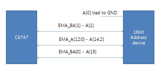
I'm using 16bit adress device.
But I don't konw pin connection.
C6747 device have EMIFA_A[12:0] interface.
How Can I use EMIFA for 16bit address device.
Pleas, inform me.
Brady.
Thanks & Regards.
Hi,
I'm using 16bit adress device.
But I don't konw pin connection.
C6747 device have EMIFA_A[12:0] interface.
How Can I use EMIFA for 16bit address device.
Pleas, inform me.
Brady.
Thanks & Regards.