This thread has been locked.

If you have a related question, please click the "Ask a related question" button in the top right corner. The newly created question will be automatically linked to this question.

Clock Configuration lcdkOMAP-L138

Other Parts Discussed in Thread: OMAPL138, OMAP-L138

Hi,

I come from the Concerto devices, so I'm new in OMAP devices.

I would like to know what is the default speed of both cores? I am asking this because I don't see any clock configuration in the example projects from the StarterWare.

In Concerto devices, I had to configure the clock for each core which I don't see here.

I took a look at the Technical Reference Manual. I can see that SYSCLK6 is the system clock for the ARM and SYSCLK1 for the DSP.

Could you give me an example of configuration if I want both core running at their maximum frequency?

Thank you for your help,
Marc 

  • Hi Marc,

    The maximum frequency at which both the ARM and DSP can run on OMAPL138 device is 456Mhz.In development environment, the clock configuration is typically done using a GEL file but this can also be done both in source code or through the boot ROM while booting. SYSCLK6 and SYSCLK1 need to maintain a fixed ratio of 1:1 which means that the frequencies of both the processors are tied together. You can find the GEL file for the 456Mhz as part of the Starterware package under the folder tools/gel.

    The procedure to connect to the LCDK is same as the procedure described here: [Use the appropriate GEL files ]

    http://processors.wiki.ti.com/index.php/How_to_connect_to_the_OMAP-L138/C6748/AM1808_EVM_board_using_CCS%3F

    Regards,

    Rahul

  • Rahul,

    Thank you for you answer!

    I tried to allow the GEL files, one for the C674x (OMAPL138_DSP.gel) and the other for the ARM9 (OMAPL138_ARM.gel).

    If I start the C674x, this is working, even if my algorithm is not running as fast as I expected. But for the ARM9, I get this error :

    ARM9_0: Output: Target Connected.
    ARM9_0: Output: ---------------------------------------------
    ARM9_0: Output: Memory Map Cleared.
    ARM9_0: Output: ---------------------------------------------
    ARM9_0: Output: Memory Map Setup Complete.
    ARM9_0: Output: ---------------------------------------------
    ARM9_0: Output: PSC Enable Complete.
    ARM9_0: Output: ---------------------------------------------
    ARM9_0: Output: PLL0 init done for Core:300MHz, EMIFA:25MHz
    ARM9_0: Output: DDR initialization is in progress....
    ARM9_0: Output: PLL1 init done for DDR:150MHz

    ARM9_0: GEL: Error while executing OnTargetConnect(): Attempted to write unmapped virtual memory at 0xB00000E4 at *((unsigned int *) (0xB0000000+0xE4))=(((((0x0<<8)|(0x1<<7))|(0x1<<6))|(0x0<<3))|(0x4<<0)) [OMAP-L138_LCDK.gel:156] at DEVICE_DDRConfig(0, 150) [OMAP-L138_LCDK.gel:435] at Set_DDR2_150MHz() [OMAP-L138_LCDK.gel:469] at Core_300MHz_mDDR_150MHz() [OMAP-L138_LCDK.gel:245] at OnTargetConnect() .

    ARM9_0: Trouble Writing Memory Block at 0xc1080000 on Page 0 of Length 0x7ff0: (Error -2030 @ 0x61706200) Internal error: Access to unknown or invalid register was requested. Restart the application. If error persists, please report the error. (Emulation package 5.0.872.0)
    ARM9_0: GEL: File: C:\Users\Marc\workspace_v5_3\ARM9_omapl138\Debug\ARM9_omapl138.out: Load failed.
    ARM9_0: Unable to terminate memory download: NULL buffer pointer at 0x320

    It looks like it is looking for a OMAP-L138_LCDK.gel whereas I didn't allow this gel file to the target configuration...
    I checked from the wiki, and my target configuration is correct. (I'm using the xds100v2 from Spectrum Digital) 

    And if I load only the OMAPL138_LCDK.gel to the ARM9 in the Target Configuration. I get the same error.

    Do you have an idea? I already checked some wiki's pages but no answer... Or some answers which didn't help much :)

    Thank you for your help,
    Marc 

  • The OMAPL138_ARM.gel file corresponds to the the EVM which has mDDR while the OMAPL138_LCDK corresponds to the LCDK which has DDR2 so you will have to use the appropriate gel to do the external memory initialization? For the DSP performance, please try to turn the L1 and L2 cache if you are using external memory or try to place you code in the DSP internal memory to obtain the best performance numbers. The gel file doesn`t turn on the cache so this needs to be done in code.

    Also there can be other factors that may be affecting device configurations so you should take the necessary precautions. What switch settings do you have ?It is recommended to set the switches to emulation boot to avoid any conflicts.

    Are you booting linux? Is uboot loading from flash on the ARM ? you can avoid boot from any other boot media by setting the switches to emulation boot.


    Regards,

    Rahul

  • Rahul,

    Thank you for your comprehensive answer.

    Ok I turned on the cache like this : 

        CacheEnable(L1PCFG_L1PMODE_32K | L1DCFG_L1DMODE_32K | L2CFG_L2MODE_256K);

    Is it correct? 

    The settings I have are from the wiki page of the LCDK (http://processors.wiki.ti.com/index.php/LCDK_User_Guide#Switches_.28SW1.29) for NAND16.
    I am not booting Linux. It is loading from RAM on the ARM. I thought there was no flash on this board, am I wrong? What is uboot?

    I guess the C674x needs the ARM to run to get his good system clock, right? Is that why it is slow if i run the C674x alone? Because with the same algorithm, I get 8µs on a Concerto C28 (150MHz) and 55µs on the C674x...

    Thank you,
    Marc 

  • Marc,

    The cache setting is correct.

    The OMAPL138 LCDK comes with uboot flashed (A user bootloader that loads linux) on the NAND flash. If you keep the boot settings as NAND then the device comes up from the boot image stored on the NAND flash. The boot image  initializes the device and loads and runs the user boot loader(u-boot). If you have SD card inserted this will then pull in the linux kernel from the SD card.You can see the logs from the boot on the serial console when you connect the USB to serial cable to the LCDK. Can you confirm that you see uboot messages when you have the switch settings to NAND boot.

    It is recommended that when you connect using JTAG, you should boot up the device in either UART/Emulation boot mode, run the GEL and then load the example.Can you try this and let us know if it worked for you.

    Regards,

    Rahul

  • Rahul,

    Thank you very much for your support, it is working well now!

    The only thing I am suprised of is that the C674x is running slower than expected. I might be doing something wrong with the system clock but I loaded the right OMAPL138_LCDK.gel...

    I figure this out if I perform my algorithm in the while() with a GPIO pin to indicate when it starts and when it finishes.
    I have like 140 lines of simple operation (multiply, soustraction, addition) which takes 55µs to execute!!
    Does the C674x really running at 300MHz? How can I check that?

    Thank you for your help,
    Marc 

  • Marc,

    If you are using the LCDK , then the clock configuration must be for 456Mhz. Have you used the optimal compiler settings?

    http://processors.wiki.ti.com/index.php/C6000_Compiler:_Recommended_Compiler_Options

    Can you analyze your code further to determine what portion of the code is consuming most number of cycles and give us a snippet that we can look at. You can try to use the Mathlib to use optimized math functions to improve on the performance of your existing code.

    Regards,

    Rahul

  • Rahul,

    I don't think this is running by default at 456MHz because if I take a look to the gel file, when OnTargetConnect() is executed it does this function :

    Core_300MHz_mDDR_150MHz();

    This mean that the core is running at 300MHz right?

    Thank you,
    Marc 

  • Rahul,

    I have the core running at 456MHz.

    To do a simple test, I just set a GPIO and clear it in the while:

    ---------------------------------------------------------------------------

    while (1)
    {

    GPIO_setOutput(GPIO_BANK7, GPIO_PIN9, OUTPUT_HIGH);

    GPIO_setOutput(GPIO_BANK7, GPIO_PIN9, OUTPUT_LOW);

    }

    ---------------------------------------------------------------------------

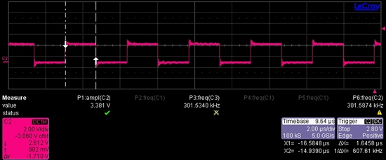
    It takes 1.6µs to set high and 1.6µs to clear it with an optimization level of 3.

    Could you try the same thing and tell me if it is normal or not?
    It seems that it takes a very long time to just set or clear a GPIO. And for 300MHz, I get 2.573µs. For 100MHz, 7.563µs. 

    Thank you for your help,
    Marc