This thread has been locked.

If you have a related question, please click the "Ask a related question" button in the top right corner. The newly created question will be automatically linked to this question.

Problem in DAC OMAP L137EVM

Hi I'm using OMAP L137 EVM
actually now I'm using the example code to program this board. To read ADC and write the DAC, I use this coding:

while (1)
{

/* Start by sending a dummy write */
while( ! ( mcasp->regs->SRCTL5 & 0x10 ) ); // Check for Tx ready
mcasp->regs->XBUF5 = 0;


/* Play Tone */
for ( msec = 0 ; msec < 1000 ; msec++ )
{
for ( sample = 0 ; sample < 48 ; sample++ )
{

/* Read then write the left sample */
while ( ! ( MCASP1_SRCTL0 & 0x20 ) );
sample_data = MCASP1_RBUF0_32BIT;
x0 = sample_data;

while ( ! ( MCASP1_SRCTL5 & 0x10 ) );
MCASP1_XBUF5_32BIT = sample_data;

}
}
}

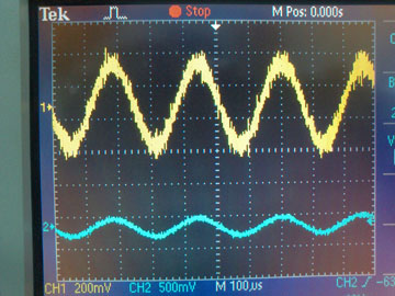
I can get the DAC result if I use this code. I can see the signal using oscilloscope if I use that coding.

My question is if I try to eliminate the "for" looping, I can't get the signal of DAC, here is the coding:
 

while (1)
{

/* Start by sending a dummy write */
while( ! ( mcasp->regs->SRCTL5 & 0x10 ) ); // Check for Tx ready
mcasp->regs->XBUF5 = 0;


/* Play Tone */

/* Read then write the left sample */
while ( ! ( MCASP1_SRCTL0 & 0x20 ) );
sample_data = MCASP1_RBUF0_32BIT;
x0 = sample_data;

while ( ! ( MCASP1_SRCTL5 & 0x10 ) );
MCASP1_XBUF5_32BIT = sample_data;

}

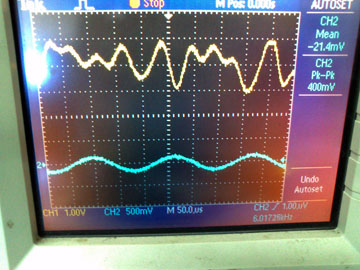
 If I use that code, I can't get the signal from DAC, Can comeone help me to find out the mistake

sorry for my bad english 

  • Hi Vincent,

    With two "For" loops, In total, you will get (1000 x 48 = )48000 samples which is perhaps a good number of samples to visualize the signal.

    If you remove the for loops, you will get data only once. With one sample, a signal graph is not possible.

    Regards,

    Shankari

    --------------------------------------------------------------------------------------------------------
    Please click the Verify Answer button on this post if it answers your question.
    --------------------------------------------------------------------------------------------------------

  • Thanks for your answer shankari,
    but I have put the code for sampling inside the "While (1)" loop
    doesn't it meant I will always get the signal data as long as I don't stop the board?

    here is the code: 

    while (1)
    {

    /* Start by sending a dummy write */
    while( ! ( mcasp->regs->SRCTL5 & 0x10 ) ); // Check for Tx ready
    mcasp->regs->XBUF5 = 0;

    /* Read then write the left sample */

    while ( ! ( MCASP1_SRCTL0 & 0x20 ) );
    sample_data = MCASP1_RBUF0_32BIT;

    x0 = sample_data;

    while ( ! ( MCASP1_SRCTL5 & 0x10 ) );
    MCASP1_XBUF5_32BIT = sample_data;

    }

    doesn't it mean the ADC wil always get the data as long as it it looped on the "while(1)" 

    actually I've tried to read the data using "printf" and it tells that the ADC always looking for the new data 

    here is the code when I tried to read the data from ADC:

    while (1)
    {

    /* Start by sending a dummy write */
    while( ! ( mcasp->regs->SRCTL5 & 0x10 ) ); // Check for Tx ready
    mcasp->regs->XBUF5 = 0;

    /* Play Tone */
    /* Read then write the left sample */
    while ( ! ( MCASP1_SRCTL0 & 0x20 ) );
    sample_data = MCASP1_RBUF0_32BIT;// & 0xffff;

    x0 = sample_data;

    printf("x0 = %d ",x0);

    }

    but why I can't make the DAC work with only using the "while(1)" loop?
    please I need your answer 

  • Hi,

    May I recommend you to understand the example code-flow better in-line with the concept/logic by yourself as a first stage.?

    The following may not be the right answer but few suggestions/pointers when looking at just the code difference.

    1. Whether the time taken to execute the instructions inside the for loops ( i.e., the counter increment and the counter comparison ) are needed ? I mean to say, you can introduce a small delay and try it out.

    2.In the previous one with "for loops, the code "check for TX ready" was executed only once while receiving 48K samples. But in the code without for loops, it was executed for receiving each sample. Please do check are there any impact due to this?

    Whether the example code is supplied by TI?

    By any chance, you modified the other portions of the code except removing for loops?

    regards,

    Shankari.


    -------------------------------------------------------------------------------------------------------

    Please click the Verify Answer button on this post if it answers your question.
    --------------------------------------------------------------------------------------------------------

  • yes, I use the example code from TI and modify it
    I only modify the for loop code by replace it  with while (1) loop

    Thanks shankari 
    I've tried  to put the code for checking Tx ready outside the while loop, and now the DAC works even without the for loop

    here is the code: 

    while( ! ( mcasp->regs->SRCTL5 & 0x10 ) ); // Check for Tx ready
    mcasp->regs->XBUF5 = 0;

    while (1)
    {

    while ( ! ( MCASP1_SRCTL0 & 0x20 ) ); 
    x0 = MCASP1_RBUF0_32BIT;

    while( ! ( MCASP1_SRCTL5 & 0x10 ) ); 
    MCASP1_XBUF5_32BIT = x0 ;

    }

    But now I'm facing another problem.  after I can make the DAC work without for loop, I tried to put IIR filter between the ADC and DAC code, and again, I can't get the result of the DAC after I put the filter equation. 
    Then I tried to simplify the equation by just averaging the signal, but the DAC produce strange signal, and it doesn't looks like the source signal.

    here is the code: 

    while( ! ( mcasp->regs->SRCTL5 & 0x10 ) ); // Check for Tx ready
    mcasp->regs->XBUF5 = 0;

    while (1)
    {
    while ( ! ( MCASP1_SRCTL0 & 0x20 ) ); 
    x0 = MCASP1_RBUF0_32BIT;

    x0 = x0 >> 16;


    y0 = (x0 + x1 + x2 + x3) / 4 ;
    x3 = x2;
    x2 = x1;
    x1 = x0;

    y0 = y0 << 16 | 0x00000000;

    while ( ! ( MCASP1_SRCTL5 & 0x10 ) ); 
    MCASP1_XBUF5_32BIT = y0 ;

    }

     if I don't devide the equation by 4 so the equation become y0 = (x0 + x1 + x2 + x3) , the DAC can work and it produce signal with  bigger amplitude than the source signal, but if I devide it by 4 (like this : y0 = (x0 + x1 + x2 + x3) / 4 ),  the signal become strange and doesn't like the source signal

    does I make any mistake?
    shouldn't it back to the original signal if I devide it by 4? 

    Here is the result if I don’t devide it by 4:

    Yellow:  DAC signal
    Blue : source signal

    And this the result if I devide it:

    Yellow:  DAC signal
    Blue : source signal

    Any idea?
    please I need your help