This thread has been locked.

If you have a related question, please click the "Ask a related question" button in the top right corner. The newly created question will be automatically linked to this question.

DM814x HSYNC & VSYNC Polarity

Dear all,

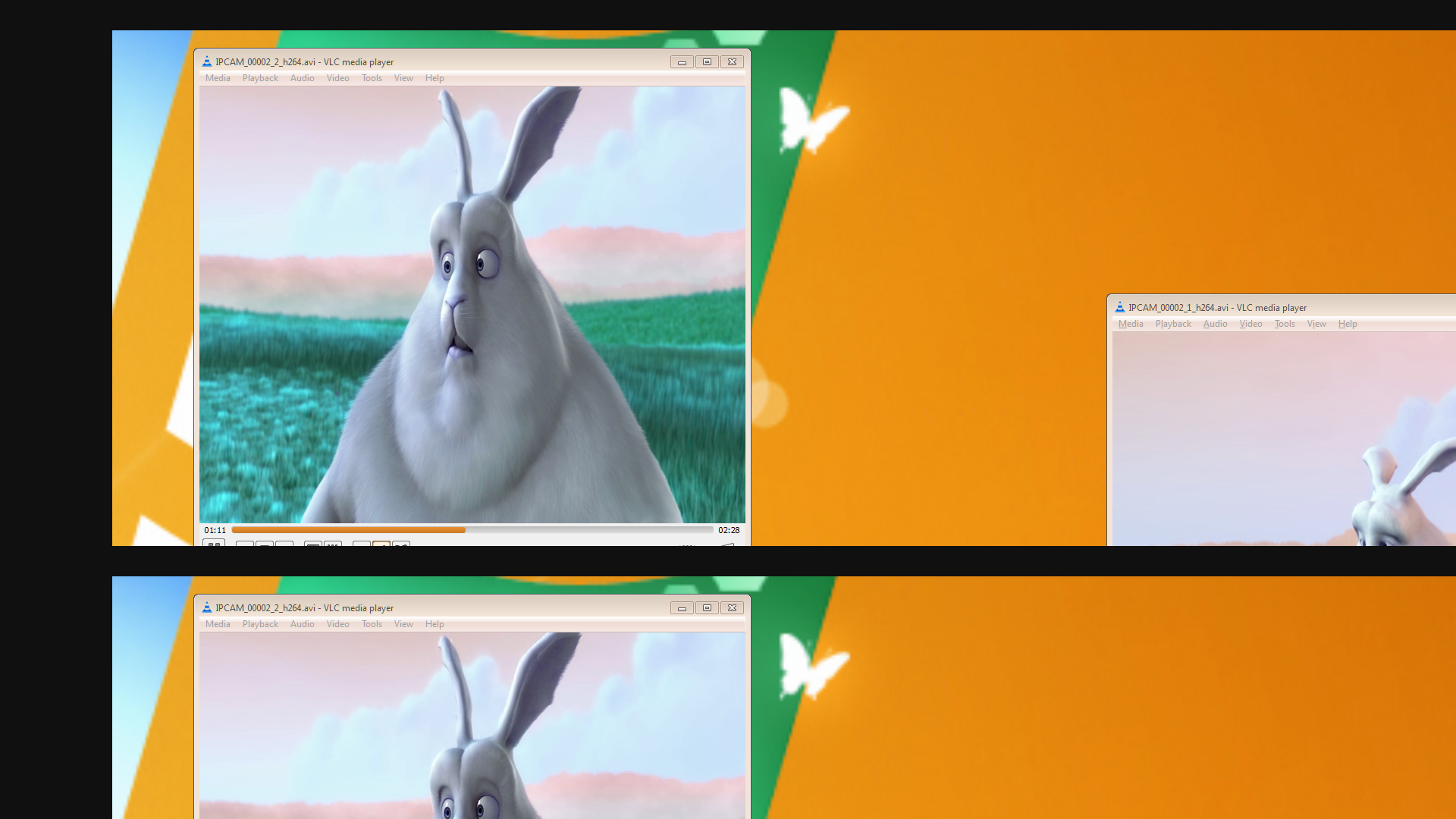
I am using a custmo Dm814x board and can capture using V4L2.  My input is a 1920x1080p60 24-bit RGB source with discrete syncs.  I capture the image below which is ok for 720 lines and then possibly then start of the next frame has been DMA'd into my buffer.

I've checked and the VIDIOC_G_FMT ioctl is returning the correct data, the capture is setup for a 1920x1080 buffer.  It looks to me like the VIP is limited to capture 720 lines?

Does anybody know where a value for this may be defined?  I'm guessing it's in the VIP Port Config but there doesn't seem to be a limit on the number of lines to capture?

Help appreciated.

Regards,

Danny Cullen 

  • Sorry, here's my captured image, it's a 24-bit, the R and B values are flipped (another issue but not related to the capture).

  • Hi danny cullen,

    I am not sure about the exact problem what you are facing.
    But one thing to hint out is that, I believe VP on DM814x can support only 16 Bit data max. not 24 bit. !!
    Please do check with your ISS TRM from TI.

  • Hi danny,

    Check your sensor, which color pattern it supports, and based on that set the CCOLP register of ISS in Dm814x.

    That should solve your problem. For more description about Register Please check ISS TRM.

  • Hi Ravikiran, if by "sensor" you mean our input decoder chip then it outputs 24-bit RGB fine.  We use this device a lot in our products.

    I think the ISS TRM is available under NDA only, we have an NDA with TI and it's being checked so that we can get other vital documentation and sources.  I will add this to the list!!

    So, at the moment I do not know what the CCOLP register is and what it does.  Can I not access it using the VIP config setup routines?

    Kind regards,

    Danny

  • This issue was caused by using the saLoopback sample.  The capture buffers were 1920x1080 24-bit RGB, the display buffers were 1920x1080 16-bit YUYV so when the capture buffer ptr was replaced by the newly dequeued display buffer ptr the offsets though the mapped fb memory were wrong.  Offsetting the display buffer ptr to align with the base for the capture buffer ptr solve the issue.