This thread has been locked.

If you have a related question, please click the "Ask a related question" button in the top right corner. The newly created question will be automatically linked to this question.

Problem/Possible Bug: DMA source and destination addresses are changed when DMA is enabled.

Hi,

I am using the C5535 with CCS v4 to use the DMA controller 1 in ping pong mode with I2S channel 2. I am seeing something strange:

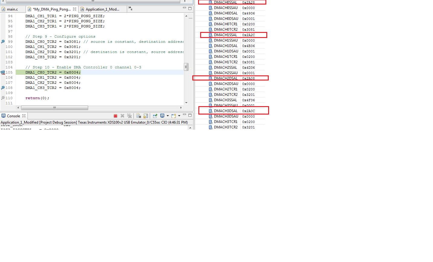
When I assign values to the DMACHnSSAL/U, DMACHnDSAL/U (source and destination registers for the DMA controller 1 channels 0-3) the values are stored correctly.

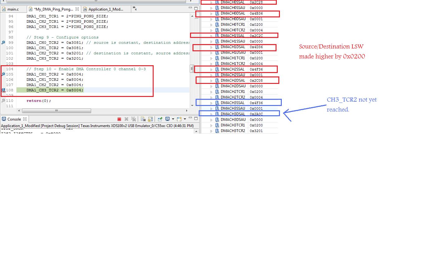
However writing a 1 to the EN (enable) bit in the TCR2 register for DMA1, causes all the values that I wrote in all of the source and destination registers to be incremented by 0x0200.

I see no reason why this should happen. Can anyone tell me why this is happening, and how to fix it? See my pictures below for clarification:


Thanks,
Nate 

  • I think this is the issue, when you are writing the enable bit, you have changed the source and destinations modes to auto increment and the dma starts running, so the source and destination address will change as you have observed.  You need to maintain your desired src dst modes when you write to TCR2 in the enable step.

    PS. Version 3.01 of the CSL has some pretty decent working example for DMA/I2S configuration.

    -S

  • Shawn S. said:

    I think this is the issue, when you are writing the enable bit, you have changed the source and destinations modes to auto increment and the dma starts running, so the source and destination address will change as you have observed.  You need to maintain your desired src dst modes when you write to TCR2 in the enable step.


    Thanks for the response Shawn. I don't think this is the issue. From the technical reference for initializing the DMA steps 9-11 (the last steps):

    9. Configure DMACHmTCR2 accordingly. Through this register you can specify the source and destination addressing modes and burst mode. You can also enable automatic reload, event synchronization, CPU interrupts and Ping-Pong mode. Note that you must keep EN = 0 and SYNCMODE = 0 during this step.
    10. If the DMA channel is servicing a peripheral, ensure that the corresponding peripheral is not active and hence not generating synchronization events.
    11. Enable the DMA channel by setting EN = 1 (and SYNCMODE = 1 if using synchronization events).


    As you can see the last step (step 11) just says to enable the EN bit and SYNCMODE bit. Setting the source and destination addressing mode bits (DSTAMODE/SRAMODE) happens in step 9.
    I recognize that you are suggesting that I set the DSTAMODE/SRAMODE bits in TCR2 as the last step in the initialization process for the DMA, but you can see from the technical reference that it is advised to only set the EN and SYNCMODE bits as the last step in the DMA initialization process. That is what I am doing, but the contents of the address registers changes. 

    Also, when I set the EN and SYNCMODE bits in TCR2 as step 11- if what you say is true - all of the contents of the source and destination address registers should continuously increment (because I left the DSTAMODE/SRAMODE bits as 0 in my step 11) -  but they don't. They simply get incremented by 0x0200 when the EN bit is set, and remain that way. 


    I will try what you are implying,  and I will try to set the DSTAMODE/SRAMODE while I also set the EN and SYNCMODE bits, and I will report my findings. I do not expect this to work however, and if it does, then the technical reference  has a serious error within it. 

    I do appreciate the response though Shawn!

    Shawn S. said:

    PS. Version 3.01 of the CSL has some pretty decent working example for DMA/I2S configuration.

    There are separate I2S and DMA projects - and while they may help some people, they have not helped me very much :(

    I would appreciate if anyone else has any insight into this as well!

    Nate 
     

  • I just checked the CSL in the DMA_start( ) function, when it starts the DMA it does the following:

    hDMA->dmaRegs->DMACH0TCR2 |= CSL_DMA_DMATCR2_DMASTART_SYNC_MASK;

    the above equates to DMA1_CH0_TCR2 |= 0x8004;

    So i think the key thing is that when you enable the DMAs you need to use a |= (OR equals) not a straight =

    -S


  • Update:

    Shawn - your suggested fix did indeed work. I see in your second post now why that is!! Ill have to go back and and carefully check whether I am using = or |= for my register assignments!!! tricky! 

    Basic Question: How do you know when to use =, and when to use |= ? The technical reference doesnt specify. 

    Second question: if the DSTA/SRCAMODE bits are set to auto-increment, then do the actual SSAL/SSAU/DSAL/DSAU  registers get incremented? Or do they always have the base address values stored in them no matter how you set the DSTA/SRCAMODE bits? 

    Thanks so much!!!

    Nate 

  • Use the |= when you only want to set specific bits and not disturb other bits which you have set in previous steps.  This will then meet the requirement of the tech reference that you don't write the anything new to the DMACHmTCR2 configuration (src mode, dst mode etc) when setting EN=1.

    Once the dma starts running, you will see the SSAL/SSAU/DSAL/DSAU values change, they will not stay at their base address.

    -S

  • As an aside, the CSL does have an example that combines I2S and DMA:

    C:\c55xx_csl_3.01\ccs_v4.0_examples\i2s\CSL_I2S_DMAExample

    This example combined with the others should contain what you need. Also, using the CSL alleviates you from having to dig deep into manuals and figure out bit settings for control registers.  The CSL provides a configuration structure which uses enums, makes it easier to change how the dma operates.

    In general, here's my code's startup sequence when using the CSL:

    /* Initialize I2S */
    I2S_init();
    //uses I2S_open( ) and I2S_setup( )


    // setup the dma for the codec.
    setupPassFail=CodecIO_i2s_DMA_setup();
    if (CSL_SOK!= setupPassFail)
    {
    LOG_printf(&trace,
    "I2S Dma Setup Failed!!\n");
    }

    /*
    Prime Codec I/O. (i.e. start the DMAs)
    */

    IRQ_clear(DMA_EVENT);
    /* Enabling Interrupts */
    IRQ_enable(DMA_EVENT);

    I2S_transEnable(hI2s_CodecIO, TRUE);
    status
    = DMA_start(dmaLeftRxHandle);
    status
    = DMA_start(dmaRightRxHandle);
    status
    = DMA_start(dmaLeftTxHandle);
    status
    = DMA_start(dmaRightTxHandle);

    -S

  • Awesome - Thanks for all the help Shawn!! 
    The problem I have with the CSL is that there is no guide on actually using the CSL (what order the functions go in, how to use the CSL to do X, or Y...).  When I used the CSL, for whatever reason, things tended not to work - this is why it just made more sense to me to work with individual registers.  


    your psuedo-code looks similar to mine. Particularly helpful was the setting up of interrupts with the IRQ_clear and IRQ_enable functions. I was using something called VECSTART which was used in the CSL example, but which had no explanation anywhere, so I just left it in my code. 

    I tried to make a project based on the I2S/DMA example given, but I could not get it to work, so I moved onto register programming. I may go back to using the CSL since register programming is not working out for me either. 

    One more question if you have the time/answer: why is IFR1/0 cleared by writing 0xFFFF? I thought that the interrupts are represented by a 1 - which would mean clearing the interrupts would require writing 0x0000 to IFR1/0. 

    Thanks again!

     - Nate