This thread has been locked.

If you have a related question, please click the "Ask a related question" button in the top right corner. The newly created question will be automatically linked to this question.

Writing/reading registers. ICE board.

Other Parts Discussed in Thread: SYSBIOS, SYSCONFIG

Hello,

I am still very new to this board, but I am usually able to read and write registers using HWREG.

But here is my problem. I am trying to read the industrial inputs via Read_HVS(); that we can find in am335x_indcomm_utils.c file of the SDK. The program is crashing when it wants to set the FORCE bit of the MCSPI_CH(i)CONF register (i=0 spi1):

HWREG(baseAdd + MCSPI_CHCONF(chNum)) |= (MCSPI_CH0CONF_FORCE);

When the program crashes, this is the exit in the console:

[CortxA8]
Hwi handle: 0x0.
Hwi stack base: 0x800178c4.
Hwi stack size: 0x2000.
R0 = 0x481a0000  R8  = 0x00000001
R1 = 0x00000000  R9  = 0x8000f65c
R2 = 0x8000fe16  R10 = 0x481a0000
R3 = 0x00000003  R11 = 0x00000001
R4 = 0x80019a20  R12 = 0x481a0000
R5 = 0x8000fe0c  SP(R13) = 0x800197f0
R6 = 0x80001718  LR(R14) = 0x80004e0c
R7 = 0x00000000  PC(R15) = 0x80002cf4
PSR = 0x6000019f
ti.sysbios.family.arm.exc.Exception: line 176: E_dataAbort: pc = 0x80002cf4, lr = 0x80004e0c.
xdc.runtime.Error.raise: terminating execution

On the ASM side, while debugging, it is always craching at the LDR instruction:

         | McSPICSAssert:
80002ce8:|   E1A0C201 MOV             R12, R1, LSL #4
80002cec:|   E08CC101 ADD             R12, R12, R1, LSL #2
80002cf0:|   E080C00C ADD             R12, R0, R12
80002cf4:|   E59C012C LDR             R0, [R12, #300]
80002cf8:|   E3800601 ORR             R0, R0, #1048576
80002cfc:|   E58C012C STR             R0, [R12, #300]
 280     | }

I don't know if it can be helpful, but once I executed the LDR instruction, the program jumps to that kind of ASM code:

80019c10:   E59FF018 LDR             PC, 0x80019C30
80019c14:   E59FF018 LDR             PC, 0x80019C34
80019c18:   E59FF018 LDR             PC, 0x80019C38
80019c1c:   E59FF018 LDR             PC, 0x80019C3C
80019c20:   80000000 ANDHI           R0, R0, R0
80019c24:   8000CC10 ANDHI           R12, R0, R0, LSL R12
80019c28:   8000CC10 ANDHI           R12, R0, R0, LSL R12

Has anyone any idea on how to be able to write in this register [McSPI1(481A_0000) + MCSPI_CH0CONF(+12C)] avoiding that error ? It seems that the ARM cannot add 12Ch (300) to 481A0000h of register R0 or R12.

Thanks,
Paul

  • Most of the times when customers report crashes on code that was tested previously there is an issue with enabling the clocks for the peripheral.

    So did you enable the SPI module in question? You can check by accessing the register in the debugger memory window. If you are not able to do that then the module is not clocked and therefor the CPU runs into an exception if you try to access the register.

    Regards.

  • Hi Frank,

    When you say "enable the module", does it mean the same than "24.3.11.1 Module Initialization" in the TRM?

    Because in this section, it says I have to read MCSPI_SYSSTATUS. But the thing is it is crashing when I am trying to do so:
    if (HWREG(SOC_SPI_1_REGS + MCSPI_SYSSTATUS))

    It crashes when I'm trying the code before. The same happens if I use addresses directly:
    if ((0x481A0000) + (0x114))

    In the section "24.3.11.1 Module Initialization" it is saying:

    1• Hard or soft reset.
    2• Read MCSPI_SYSSTATUS.
    3• Check if reset is done.
    4• Module configuration: (a) Write into MCSPI_MODULCTRL (b) Write into MCSPI_SYSCONFIG.
    5• Before the ResetDone bit is set, the clocks CLK and CLKSPIREF must be provided to the module.

    As step 5 comes after step 4, shouldn't I normally be able to at least read the register? Looks like not because I can't even read MCSPI_SYSSTATUS.

    About the clocks not provided. I am using the McSPIClkConfig() function from mcspi.c file:
    McSPIClkConfig(SOC_SPI_1_REGS, 48000000, 6000000, MCSPI_CHANNEL_0,MCSPI_CLK_MODE_0);

    But this is the same problem, it crashes once the program is in the function at this line:
    HWREG(baseAdd + MCSPI_CHCONF(chNum)) |= MCSPI_CH0CONF_CLKG;

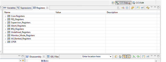
    By the way, it seems that I cannot access the register in the debugger memory window:

    Any help is welcome.

    ---

    Since I got a reply in this topic I added one line in the applMmuEntries[] variable (in red):
    SYS_MMU_ENTRY applMmuEntries[] = {

        {(void*)0x48300000,(void*)0x48300000,0,0},  //PWM - Non bufferable| Non Cacheable
        {(void*)0x48200000,(void*)0x48200000,0,0},  //INTCPS,MPUSS - Non bufferable| Non Cacheable
        {(void*)0x48100000,(void*)0x48100000,0,0},  //I2C2,McSPI1,UART3,UART4,UART5, GPIO2,GPIO3,MMC1 - Non bufferable| Non Cacheable
        {(void*)0x481A0000,(void*)0x481A0000,0,0},  //McSPI1 - Non bufferable| Non Cacheable
        {(void*)0x48000000,(void*)0x48000000,0,0},  //UART1,UART2,I2C1,McSPI0,McASP0 CFG,McASP1 CFG,DMTIMER,GPIO1 -Non bufferable| Non Cacheable
        {(void*)0x44E00000,(void*)0x44E00000,0,0},  //Clock Module, PRM, GPIO0, UART0, I2C0, - Non bufferable| Non Cacheable
        {(void*)0x4A300000,(void*)0x4A300000,0,0},  //PRUSS1 - Non bufferable| Non Cacheable
        {(void*)0x49000000,(void*)0x49000000,0,0},  //EDMA3 - Non bufferable| Non Cacheable
        {(void*)0x4A100000,(void*)0x4A100000,0,0},  //CPSW - Non bufferable| Non Cacheable
        {(void*)0xFFFFFFFF,(void*)0xFFFFFFFF,0xFF,0xFF}       
    };

    It changes absolutely nothing.

    Thanks for your time,
    Paul

  • It was probably because of clocks. I will come here and give my feedback on monday, since I don't have time now.

    Thanks.

  • It was definitely the lack of clock which was the problem. I discovered that there is this spiInit(); function in the am335x_indcomm_startup.c. So basically, my test script is now:

        spiInit();
        while(1){
            Read_HVS();
            sprintf(t_str,"%d\n",Read_HVS2());
            UARTPutString(uartInstance,t_str);
            Task_sleep(1000);
        }

    Everything is now compiling, and not crashing while executing, but Read_HVS2() always return 0. I can short any industrial inputs from J9 to 24V, it always return 0.

    Is there anything else to initialize to get this industrial inputs working ?

    It seems that spiInit() + Read_HVS() do all the stuff said here on this page except the pin muxing step and the McSPITxFIFOConfig() and McSPIRxFIFOConfig() APIs. Is there any function to perform the pinmuxing for SPI1 ?

    Thanks,
    Paul

  • Paul,

    if you look at the source for Read_HVS() and the schematics you will see that we used a GPIO to trigger the capture of HVS882 device. If you don't have the pin-mux for that GPIO and according configuration you might not get new data.

    The use of the input switches is demonstrated with the EtherCAT example. See c:\TI\am335x_sysbios_ind_sdk_1.0.0.8\sdk\protocols\ethercat_slave\ecat_appl\EcatStack\ecat_appl_cnfg.h for the pin-mux config needed. Use it like this:

            PINMUX_Config(iceMux);

    Also make sure that you call PowerGPIO() and EnableGPIOPins_ICE() in your init code. This enables GPIO3 and configures GPIO3[18] as output. Or call GPIOInit() which in turn calls this functions.

    Regards.

  • Since I was calling led_init(); in my program, therefore it had to be the pinmux which was failing. I definitely need to know more about pinmuxing.

    Do you have any link that you think could be helpful for my understanding ?

    Anyway, thank you for the time you took to answer.

    Regards,
    Paul

  • Paul,

    yes, people working with our SoC need to understand pin-muxing. Now I don't know about any specific info or training except from what is in the datasheets and TRM. At the end it is not really complex but it can be confusing. Especially if the pin-mux is done in some libs and you don't know about. So my philosophy (unfortunately not the only one) is to keep all pin-mux in a single place for the system and set it up once. Dynamic pin-mux should be avoided anyway... it is already problematic enough that we have to change pin-mux during and after boot in some cases.

    Fortunately we deliver all the source code with IA-SDK so people can step through the code and see how it is done in our examples. Otherwise let us know here if you have any specific questions. We are happy to help if time permits :-).

    regards