This thread has been locked.

If you have a related question, please click the "Ask a related question" button in the top right corner. The newly created question will be automatically linked to this question.

sampling frequency

Other Parts Discussed in Thread: TMS320C5515

Hello!

I am working with TMS320C5515 EVM under CCSv5.3.

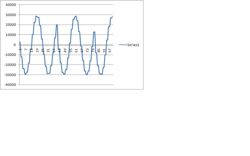
I would want to know how can I change the sampling Frequency of AIC3204. I was developing a program and I thought that It was configured to 48KHz sampling Frequency. However, when entering with a 1KHZ tone input, in the output I get a signal that would be of 1 Khz If the sampling frequency was 24KHz. not 48KHz.

I want to know If I have the sampling frequency of the aic3204 bad configured, or If there are another problem different by that one.

I put the configuration here:


AIC3204_rset( 0, 0x00 );

AIC3204_rset( 27, 0x00 );

AIC3204_rset( 4, 0x07 );

AIC3204_rset( 6, 0x20 );

AIC3204_rset( 7, 0 );

AIC3204_rset( 8, 0 );

AIC3204_rset( 5, 0x92 );

AIC3204_rset( 13, 0x00 );

AIC3204_rset( 14, 0x80 );

AIC3204_rset( 20, 0x80 );

AIC3204_rset( 11, 0x88 );

AIC3204_rset( 12, 0x82 );

AIC3204_rset( 18, 0x88 );

AIC3204_rset( 19, 0x82 );

and the function is:

nt16 AIC3204_rset( Uint16 regnum, Uint16 regval )

{

Uint8 cmd[2];

cmd[0] = regnum & 0x007F;

cmd[1] = regval;

return EVM5515_I2C_write( AIC3204_I2C_ADDR, cmd, 2 );

}

  • Since you are configuring codec as slave (Register 27 clock settings), sampling frequency depends on the clocks generated by I2S. What is the CPU clock and I2S clock divider values you are configuring?. Or are you intended to configure codec as master?.

    Pratap.

  • Sorry,

    this is done later:

    /* I2S settings */

    I2S2_SRGR = 0x0015;

    I2S2_ICMR = 0x0028;

    // Enable interrupts

    I2S2_CR = 0x8012;

    // 16-bit word, Master, enable I2C


    I may think that is master configured?

  • After that in a loop, it is done the next:

    /* Read Digital audio input */

    while((Rcv & I2S2_IR) == 0); // Wait for receive interrupt to be pending

    data3 = I2S2_W0_MSW_R;

    // 16 bit left channel received audio data

    data4 = I2S2_W1_MSW_R;

    // 16 bit right channel received audio data

    /* Write Digital audio input */

    while((Xmit & I2S2_IR) == 0); // Wait for receive interrupt to be pending

    I2S2_W0_MSW_W = data3;

    // 16 bit left channel transmit audio data

    fprintf(f,"\n%i",data3);

    I2S2_W1_MSW_W = data4;

    This is a loop where the input of Stereo Input 1 is looped to Headphones output.

    However, When I put a 1KHz signal at the input, I get the next at the output:


    Then, if it well configured at 48KHz sampling, I don't know why there is not a period each 48 samples since the input is a sine at 1KHz.


  • The settings you have shown match settings I have used with CPU as master and CPU clock at 100Mhz.  Are you running the CPU at 100Mhz?

    Also, try a run without the fprintf( ) statement in your C code, that printf( ) will slow down your entire for loop, it is possible your just missing data.

    -S

    scratch notes:

    AIC3204_rset( 0, 0x00 ); 
    AIC3204_rset( 27, 0x00 );  BCLK is input, WCLK as input
    AIC3204_rset( 4, 0x07 );   BCLK is input to PLL, PLL Clock Is CODEC_CLKIN
    AIC3204_rset( 6, 0x20 );   J = 32
    AIC3204_rset( 7, 0 );      D=0
    AIC3204_rset( 8, 0 );   D=0
    AIC3204_rset( 5, 0x92 );  P=1 R=2
    AIC3204_rset( 13, 0x00 ); DOSR hi =0
    AIC3204_rset( 14, 0x80 ); DOSR low = 128
    AIC3204_rset( 20, 0x80 ); AOSR 128
    AIC3204_rset( 11, 0x88 ); NDAC = 8
    AIC3204_rset( 12, 0x82 ); MDAC = 2
    AIC3204_rset( 18, 0x88 ); NADC =8
    AIC3204_rset( 19, 0x82 ); MADC =2
  • I also thought about fprintf commmand is affecting the code. If this would be the case, which command should I use to store the sample in an extern file?

  • Try saving the input samples in an Array and run the for loop for a set number of times & when the for loop is finished, use the memory view and "store to file" to store the values to a file.

  • It was the fprintf command. I ran it without this command and it works fine. To store the samples, I save it in a buffer declared as global and then I did the loop for fprintf in main function.

  • Hi There,

    I am using C5515 EVM. I am having trouble in getting audio samples into my program. I've verified my config with yours (as shown above),  all looks OK, but no audio. For the stereo In,  I am using J9/J12 inputs and external microphone is connected.

     Your help will be much appreciated.  


    Thanks,

    Krishna.


  • Hello!

    I think that your problem may be the signal route. You should verify the ADC routing with the resgisters of AIC3204.

    (page 1 registers 53 53 54...)

    Hope this helps

  • Hi There,

    Thanks for the reply.

    Please find below my AIC3204 config. Please have a look and let me know if something is not right.


      AIC3204_rset(  0, 0x00 );      // Select page 0
        AIC3204_rset(  1, 0x01 );      // Reset codec
        AIC3204_rset(  0, 0x01 );      // Select page 1
        AIC3204_rset(  1, 0x08 );      // Disable crude AVDD generation from DVDD
        AIC3204_rset(  2, 0x00 );      // Enable Analog Blocks
        // PLL and Clocks config and Power Up 
        AIC3204_rset(  0, 0x00 );      // Select page 0
        AIC3204_rset( 27, 0x00 );      // BCLK and WCLK is set as i/p to AIC3204(Slave)
        AIC3204_rset(  4, 0x07 );      // PLL setting: PLLCLK <- BCLK and CODEC_CLKIN <-PLL CLK
        AIC3204_rset(  6, 0x20 );      // PLL setting: J = 32
        AIC3204_rset(  7, 0 );         // PLL setting: HI_BYTE(D)
        AIC3204_rset(  8, 0 );         // PLL setting: LO_BYTE(D)
        // For 48 KHz sampling
        AIC3204_rset(  5, 0x92 );      // PLL setting: Power up PLL, P=1 and R=2
        AIC3204_rset( 13, 0x00 );      // Hi_Byte(DOSR) for DOSR = 128 decimal or 0x0080 DAC oversamppling
        AIC3204_rset( 14, 0x80 );      // Lo_Byte(DOSR) for DOSR = 128 decimal or 0x0080
        AIC3204_rset( 20, 0x80 );      // AOSR for AOSR = 128 decimal or 0x0080 for decimation filters 1 to 6
        AIC3204_rset( 11, 0x84 );      // Power up NDAC and set NDAC value to 4
        AIC3204_rset( 12, 0x82 );      // Power up MDAC and set MDAC value to 2
        AIC3204_rset( 18, 0x84 );      // Power up NADC and set NADC value to 4
        AIC3204_rset( 19, 0x82 );      // Power up MADC and set MADC value to 2
        // DAC ROUTING and Power Up
        AIC3204_rset(  0, 0x01 );      // Select page 1
        AIC3204_rset( 12, 0x08 );      // LDAC AFIR routed to HPL
        AIC3204_rset( 13, 0x08 );      // RDAC AFIR routed to HPR
        AIC3204_rset(  0, 0x00 );      // Select page 0
        AIC3204_rset( 64, 0x02 );      // Left vol=right vol
        AIC3204_rset( 65, 0x00 );      // Left DAC gain to 0dB VOL; Right tracks Left
        AIC3204_rset( 63, 0xd4 );      // Power up left,right data paths and set channel
        AIC3204_rset(  0, 0x01 );      // Select page 1
        AIC3204_rset( 16, 0x00 );      // Unmute HPL , 0dB gain
        AIC3204_rset( 17, 0x00 );      // Unmute HPR , 0dB gain
        AIC3204_rset(  9, 0x30 );      // Power up HPL,HPR
        AIC3204_rset(  0, 0x00 );      // Select page 0
        EVM5515_wait( 500 );         // Wait
        // ADC ROUTING and Power Up
        AIC3204_rset(  0, 0x01 );      // Select page 1
        AIC3204_rset( 52, 0x30 );      // STEREO 1 Jack
                                 // IN2_L to LADC_P through 40 kohm
        AIC3204_rset( 55, 0x30 );      // IN2_R to RADC_P through 40 kohmm
        AIC3204_rset( 54, 0x03 );      // CM_1 (common mode) to LADC_M through 40 kohm
        AIC3204_rset( 57, 0xC0 );      // CM_1 (common mode) to RADC_M through 40 kohm
        AIC3204_rset( 59, 0x0f );      // MIC_PGA_L unmute
        AIC3204_rset( 60, 0x0f );      // MIC_PGA_R unmute
        AIC3204_rset(  0, 0x00 );      // Select page 0
        AIC3204_rset( 81, 0xc0 );      // Powerup Left and Right ADC
        AIC3204_rset( 82, 0x00 );      // Unmute Left and Right ADC
       
        AIC3204_rset( 0,  0x00 );   
        EVM5515_wait( 200 );  // Wait


    Thanks again.


  • Hello, there is only a pair of things different from your code to mine:

    I put this:

     AIC3204_rset( 11, 0x88 );      // Power up NDAC and set NDAC value to 8

     AIC3204_rset( 18, 0x88 );      // Power up NADC and set NADC value to 8

    Instead of

    AIC3204_rset( 11, 0x84 );      // Power up NDAC and set NDAC value to 4

     AIC3204_rset( 18, 0x84 );      // Power up NADC and set NADC value to 4


    However, I think that It wouldn't be the problem.

    Is the audio source connected to Stereo In 1 (J9) working?

  • How did you connect the external microphone?

  • Thanks for the quick reply. I am connecting External Microphone to J9 Jack. 

  • External Microphone connection is not working with both the inputs. I've Tried different things but no luck. Do you think problem is with the electrical connection?

  • You can try to connect another audio source (mobile pone, mp3) with minijag connector to try if it Works.

     In which connector are you trying to listen the audio¿ You have to use J4 (Headphone connector).

  • I am using normal PC Microphone. Yes, I connected speakers to J4. Also, I am putting a break point in my program and looking at the magnitude of the samples coming into the DSP loop.  I am using example programs given in the 5515_EVM_v1.  Also, When I put a break point and plot the captured samples they are very small in magnitude with values varying between +/-80 to +/-120. I've tried the similar program to capture the microphone samples they are working fine and I can see the audio and its FFT displayed correctly. The problem lies in the Stereo IN input.

    Your help is much appreciated. As I am really stuck here.

    Thanks.

  • Then, with the same program but connecting another audio source, the program is working? Could you listen the audio?

    Further, the samples captured seems very small to hear anything. You can also introduce a known signal (1KHz sinus) at the input and capture the simple to verify that the signal at the output is correct.

    I don't know what could be wrong.


  • Hi There,

    Thank you again for the feedback. I appreciate that.

    Coming to the actual problem, I want to use Stereo In1 or Stereo In2 as the audio sources. I don't understand why these inputs are not working. It is a brand new C5515EVM board.  I am suspecting something wrong in my configuration. Could you please post your configuration file so that I can  check against yours? If u have some example programs to capture the samples from Stereo In1 or In2 that would be great also.


  • Int16 aic3204_loop_stereo_in1( )

    {

        /* Pre-generated sine wave data, 16-bit signed samples */

        Int16 j, i = 0;

        Int16 sample, data1, data2, data3, data4;

           /* Configure AIC3204 */

        AIC3204_rset(  0, 0x00 );      // Select page 0

        AIC3204_rset(  1, 0x01 );      // Reset codec

        AIC3204_rset(  0, 0x01 );      // Point to page 1

        AIC3204_rset(  1, 0x08 );      // Disable crude AVDD generation from DVDD

        AIC3204_rset(  2, 0x00 );      // Enable Analog Blocks

        // PLL and Clocks config and Power Up 

        AIC3204_rset(  0, 0x00 );      // Select page 0

        AIC3204_rset( 27, 0x00 );      // BCLK and WCLK is set as i/p to AIC3204(Slave)

        AIC3204_rset(  4, 0x07 );      // PLL setting: PLLCLK <- BCLK and CODEC_CLKIN <-PLL CLK

        AIC3204_rset(  6, 0x08 );      // PLL setting: J

        AIC3204_rset(  7, 0 );         // PLL setting: HI_BYTE(D = 0)

        AIC3204_rset(  8, 0 );         // PLL setting: LO_BYTE(D) = 0

        // For 48 KHz sampling

        AIC3204_rset(  5, 0x92 );      // PLL setting: Power up PLL, P=1 and R=2

        AIC3204_rset( 13, 0x00 );      // Hi_Byte(DOSR) for DOSR = 128 decimal or 0x0080 DAC oversamppling

        AC3204_rset( 14, 0x80 );      // Lo_Byte(DOSR) for DOSR = 128 decimal or 0x0080

        AIC3204_rset( 20, 0x80 );      // AOSR for AOSR = 128 decimal or 0x0080 for decimation filters 1 to 6

        AIC3204_rset( 11, 0x88 );      // Power up NDAC and set NDAC value to 8

        AIC3204_rset( 12, 0x82 );      // Power up MDAC and set MDAC value to 2

        AIC3204_rset( 18, 0x88 );      // Power up NADC and set NADC value to 8

        AIC3204_rset( 19, 0x82 );      // Power up MADC and set MADC value to 2

        // DAC ROUTING and Power Up

        AIC3204_rset(  0, 0x01 );      // Select page 1

        AIC3204_rset( 12, 0x08 );      // LDAC AFIR routed to HPL

        AIC3204_rset( 13, 0x08 );      // RDAC AFIR routed to HPR

        AIC3204_rset(  0, 0x00 );      // Select page 0

        AIC3204_rset( 64, 0x02 );      // Left vol=right vol

        AIC3204_rset( 65, 0x00 );      // Left DAC gain to 0dB VOL; Right tracks Left

        AIC3204_rset( 63, 0xd4 );      // Power up left,right data paths and set channel

        AIC3204_rset(  0, 0x01 );      // Select page 1

        AIC3204_rset( 16, 0x06 );      // Unmute HPL , 6dB gain

        AIC3204_rset( 17, 0x06 );      // Unmute HPR , 6dB gain

        AIC3204_rset(  9, 0x30 );      // Power up HPL,HPR

        AIC3204_rset(  0, 0x00 );      // Select page 0

        EVM5515_wait( 500 );         // Wait

        // ADC ROUTING and Power Up

        AIC3204_rset(  0, 0x01 );      // Select page 1

        AIC3204_rset( 52, 0x30 );      // STEREO 1 Jack

                               // IN2_L to LADC_P through 40 kohm

        AIC3204_rset( 55, 0x30 );      // IN2_R to RADC_P through 40 kohmm

        AIC3204_rset( 54, 0x03 );      // CM_1 (common mode) to LADC_M through 40 kohm

        AIC3204_rset( 57, 0xC0 );      // CM_1 (common mode) to RADC_M through 40 kohm

        AIC3204_rset( 59, 0x0f );      // MIC_PGA_L unmute

        AIC3204_rset( 60, 0x0f );      // MIC_PGA_R unmute

        AIC3204_rset(  0, 0x00 );      // Select page 0

        AIC3204_rset( 81, 0xc0 );      // Powerup Left and Right ADC

        AIC3204_rset( 82, 0x00 );      // Unmute Left and Right ADC   

        AIC3204_rset( 0,  0x00 );   

        EVM5515_wait( 200 );  // Wait

        /* I2S settings */

        I2S2_SRGR = 0x0015;

        I2S2_ICMR = 0x0028;    // Enable interrupts

        I2S2_CR   = 0x8012;    // 16-bit word, Master, enable I2C   

        /* Play Tone */

        for ( i = 0 ; i < 5 ; i++ )

        {

            for ( j = 0 ; j < 1000 ; j++ )

            {

                for ( sample = 0 ; sample < 48 ; sample++ )

                {

    /* Read Digital audio input */

    while((Rcv & I2S2_IR) == 0);   // Wait for receive interrupt to be pending

                    data3 = I2S2_W0_MSW_R;  // 16 bit left channel received audio data

                  data4 = I2S2_W1_MSW_R;  // 16 bit right channel received audio data

    /* Write Digital audio input */

                    while((Xmit & I2S2_IR) == 0);  // Wait for receive interrupt to be pending

                  I2S2_W0_MSW_W = data3;  // 16 bit left channel transmit audio data

                  I2S2_W1_MSW_W = data4;  // 16 bit right channel transmit audio data
                }
            }
    }

        /* Disble I2S */
        I2S0_CR = 0x00;

        return 0;

    }