This thread has been locked.

If you have a related question, please click the "Ask a related question" button in the top right corner. The newly created question will be automatically linked to this question.

What sets USB DEV_CTL Host Mode bit 2?

Other Parts Discussed in Thread: AM3358

I am currently trying to use u-boot (u-boot-2012.10-psp05.06.00.00) on AM3358 processor custom board to test out our USB interfaces.  When I run the 'usb start' command I get the following:

U-Boot# usb start
(Re)start USB...
Error, couldn't init Lowlevel part
U-Boot#

I have traced the reason for this error to a timeout in usb_lowlevel_init routine in u-boot-2012.10-psp05.06.00.00\drivers\usb\musb-new\musb_uboot.c. The timeout occurs because bit 2 of the DEV_CTL register has not been set to 1. 

The description for bit 2 Host Mode bit is as follows: "This read-only bit is set when the USB controller is acting as a Host.".

So my question is really, what causes or what has to happen successfully in order for the hardware to set this bit to 1? Also, if there are any hardware lines I should be probing which should be in a certain state for the Host Mode bit to be 1, let me know.

As a software engineer, I'm just delving into the USB functionality in depth now, but thought I would send this question out.

  • First check the HW if the USBx_ID pin is grounded without any resistor.

    And if there is >120uF capacitor on USBx_VBUS line.

  • Thanks for you quick response with suggestions.  I need to check with hardware engineer tomorrow.  But just to check, USBx_ID pin being grounded without a resistor is bad or is this good and it should be grounded without a resistor?

  • I am sorry for the rush and unclear response. to let the controller works in host mode, the ID pin should be grounded, and VBUS should have > 120uF capacitance, which is required in the USB20 Specs.

  • Our hardware engineer has confirmed the hardware design is as per your guidance. I read another forum post stating that VBUS source should be off when trying to start a host session, so we will check that too.

    I guess there must be a set of condtions that need satisfied in order the for the DEV_CTL bit 2 to be set.  I am sure I need to read more about Host Negotiation.

  • Hi John,
     
    For Host mode a power switch should be used on VBUS: power input tied to +5V supply, power output tied to USB connector VBUS, and control signal (active high) driven by AM335X USBx_DRVVBUS pin. Also processor pin USBx_VBUS must have feedback from the VBUS rail. Plus what Bin already mentioned above.
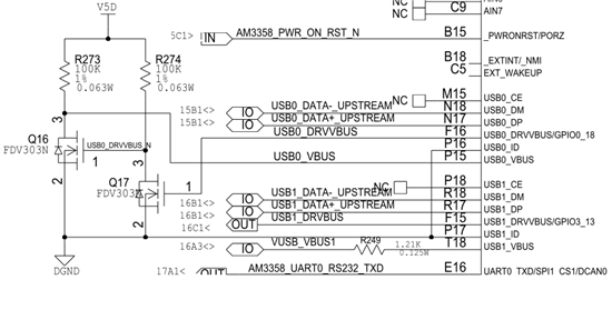
  • Hi, thanks for your suggestions.  I have pasted the part of our schematic below for the USB signals coming from the processor;  I believe it has been implemented as per the guidance you and Bin gave.  One thing which I should have mentioned earlier, is that we have a USB hub connected to USB0 controller, so I don't know if this would need to be catered for differently.

    Thanks

  • This schematic will work fine if you have an on-board self-powered USB device attached. Is your hub on-board?
  • The Hub is indeed on the same board, using Cypress CY7C65632-48AXCT hub chip.

  • Can you see USB0_DRVVBUS going active? Can you check the voltage at USB0_VBUS? It should be above 4.4V.
  • Hi Biser,

    thanks for your continued support. Due to a number of factors, it will be Tuesday before I can check this.

  • I think Biser may have a valid point with respect to VBUS voltage.  The USB OTG specification requires the AM335x VBUS input impedance to be 40k - 100k ohms so the 100k ohm resistor R273 may be too large to get a voltage above the VBUS valid threshold.

    Regards,
    Paul

  • Thanks Biser and Paul,

    We have looked at the two signals, USB0_DRVVBUS and USB0_VBUS and noted the following:

    • USB0_DRVVBUS => shows a 100ms low to high pulse of 3.3V
    • USB0_VBUS => shows a 100ms low to high pulse of approx 2.3V (which is much lower than required)

    As per your comment Paul we will look into the resistor and see about changing it to a lower one.

    Thanks

    John

  • Here is some additional info from the resistor changes we did:

    Changed R273 to be 56K instead of 100K: USB0_VBUS pulsed at approx 2.8V for 100 ms; so this was an increase but not as much as we would expect.

    Changed R273 to be be a 5K instead this time: USB0_VBUS went to approx 4.5V and stayed there, i.e. there was no pulse this time. 

    So the USB0_VBUS looks better, but 'usb start' in u-boot still results in the timeout I mentioned before, with it timing out waiting for Host Mode (bit 2) of DEVCTL register still to be set.

  • John,

    The 100ms you are seeing is a design feature of the MUSB core.

    After the assertion of the relevant DRVVBUS signal, the core will sample USBn_VBUSIN waiting for the voltage level to meet or exceed VBUS_VALID (~4.4V). If VBUS_VALID is not reached within this 100ms timeout, the core will assume that the power source for VBUS has an error or is in OC mode and will turn it back off. 4.5V is very close to the VBUS_VALID limit, and below the USB specified VBUS droop parameters, so I would work on getting closer to 5V.

    As for the Host/Device mode timeout in uBoot, did you verify that USBn_ID is grounded?

  • Sorry for the delayed response (some priorities got switched around); thanks to everyone for the responses and help so far; not sure if anyone still watching this after such a delay but...

    Thanks DK; in your response to your suggestions:

    VBUS0 is staying at 4.5V all the time after doing the 'usb start' command, so that suggests to me that it has achieved VBUS_VALID within the 100ms otherwise it would have be turned off and sitting at 0V I guess.

    USB0_ID is indeed grounded.


  • Maybe others have any comments, but I cannot think of any obvious.

    So I think there is another thing to check is Linux kernel - Is it possible to bring up SDK kernel on your board to check the USB port in case there is anything wrong in u-boot?

    'cat /proc/driver/musb_hdrc.0' command in Linux will dump the status of MUSB0.

  • John,

    4.5V is still too low. VBUS needs to be @ 4.75V MIN (5.0V nominal) or devices may fail to function.

  • John, do you have the whole value of DEVCTL while u-boot is stuck in the loop?

  • Hi DK, we will try push the voltage up higher as you suggest.

    Hi Bin Liu, our device is actually going to boot Windows Embedded Compact so I haven't ported the Linux build for our hardware, just the U-boot build which we are using because it is a powerful tool for some hardware bring up activities. 

    The DEVCTL register is showing the value 0x19 after the loop times out, which I believe suggests that VBUS is considered valid.  Before the loop is entered, the DEVCTL register is 0x81.

    Thanks

    John

  • Quick update, we changed R273 resistor to be 470 Ohm instead of the 5K resistor we had put on before.  This resulted in VBus being 4.99V , so we have the higher voltage now.  Still get the timeout waiting on the Host Mode bit in DEVCTL register though.  I need to go read more about the USB interaction and understand what U-boot is doing to setup the USB.

  • John,

    0x19 on DEVCTL tells MUSB controller is locked on a valid vbus, and ready to transit to host mode when it detects a USB device connected (DP/DM gets pulled up by the device). But MUSB does not sense the DP/DM pullup so DEVCTL[2] is not set.

    Now I just realized you have a HUB chip on board, so either u-boot does not support on-board HUB (I will try to find it out), or your HUB related design has issues.

    If u-boot supports on-board HUB, you don't even need to connect any USB device on your board, 'usb start' should report '1 usb device found' which is the HUB device. That is what I am seeing on EVM when connected a external HUB. Which makes sense.

    Just for testing purpose, is it possible to bypass the HUB chip on your board to see if any USB device could be detected?

  • Hi Bin-Liu,

    we have the hub working now :-). Thanks to everyone for their help and support throughout this issue.  I have written details of the work done today which got us towards a working Hub in u-boot, with the fundamental step being the increased VBUS voltage step encountered earlier in the thread..

     We tried using USB1 interface (the hub interface in our design is USB0) and this worked when I plugged in a mouse,
    it also worked when I plugged in an external USB hub device and also, when connecting the mouse to the external hub, it could see that too.  So this proved to
    us that our build of u-boot could deal with a hub. We hadn't previously tried USB1 because it was only brought out through board pins so I needed to get a
    special connector board made up to connect a device to this.
     
    We then focussed on our USB0 hub itself and found one of the signals to the hub was putting it into a test mode which we believe was causing the problem,
    we removed some resistors to put this signal to a desired state and once I did a u-boot build that only configures USB0 (had to disable USB1 for it to 
    work - which I need to understand why)  then 'usb start' ran successfully and detected the hub which was then shown by running usb tree. I connected
    a mouse and a keyboard to the two exposed hub ports and got the following usb tree print out (as proof :-) ): 

    U-Boot# usb tree

    Device Tree:
      1  Hub (480 Mb/s, 100mA)
      |   USB2.0 Hub
      |
      +-2  Human Interface (1.5 Mb/s, 70mA)
      |    Dell Dell USB Keyboard
      |
      +-3  Human Interface (1.5 Mb/s, 100mA)
           Genius Optical Mouse


  • John, great progress! Thanks for the update.

  • Hey John, 

    Thx for your post. The disabling of the other USB did the trick to get the other controller to work.

    You ever figured out why the not needed USB must be disabled? 

    This is really weird and usually I don't like such solutions where I don't understand why this needs to be done like this.

    Regards,

    Thilo

  • Thilo,

    The reason is that only ONE usb port can be in host mode in u-boot.

    Here is the details: http://e2e.ti.com/support/arm/sitara_arm/f/791/p/345553/1208674.aspx#1208674