This thread has been locked.

If you have a related question, please click the "Ask a related question" button in the top right corner. The newly created question will be automatically linked to this question.

C6678 external loopback test - test all links

Hi,

I am currently testing the TSIP on a prototype board with the C6678 DSP. The test I am implementing involves connecting all the TSIP signals to an FPGA and looping the TX data signals from the DSP back onto the RX signals back to the DSP.

The FPGA provides a 16.384MHz clock to each clock pin on the DSP and a Frame Sync signal that pulses from high to low every 2048 clock cycles. The frame sync signal is sent to each FS pin on the DSP.

I run the test project "TSIP_testProject" provided in the C6678 PDK package to test my setup with the following configuration settings:

/* Provide size information for TSIP */
sizeCfg->maxChannels = TSIP_MAX_TIMESLOTS;
sizeCfg->subFrameSize = 8;
sizeCfg->wordSize = 8;

/* Global configuration */
cfg->testMode = FALSE;
cfg->testModeSelect = CSL_TSIP_TESTMODE_DATA_LOOPBACK;
cfg->clkRedund = CSL_TSIP_CLKD_REDUN;
cfg->endian = CSL_TSIP_ENDIAN_LITTLE;
cfg->priority = CSL_TSIP_PRI_0;
cfg->maxPriority = CSL_TSIP_PRI_0;

cfg->sizeCfg = sizeCfg;
cfg->maxPhase = 10;
cfg->subFrameCallout=NULL;
cfg->cxt=NULL;

/* Transmit configuration */
cfg->tx.channel = deviceWhoAmI();
cfg->tx.frameSize = CSL_TSIP_FRAMESIZE_128;
cfg->tx.tsPerFrame = 256;
cfg->tx.clkSrc = CSL_TSIP_CLKSRC_A;
cfg->tx.dataDelay = 0;
cfg->tx.bdxDelay = CSL_TSIP_DLY_CTRL_DISABLE;
cfg->tx.idleDrive = CSL_TSIP_XMTDIS_HIGHIMP;
cfg->tx.fsyncPol = CSL_TSIP_FSYNCP_ALOW;
cfg->tx.fsyncClkPol = CSL_TSIP_CLKP_RISING;
cfg->tx.clkPol = CSL_TSIP_CLKP_FALLING;
cfg->tx.dataRate = CSL_TSIP_DATARATE_8M;
cfg->tx.clkMode = CSL_TSIP_CLKM_DBL;
cfg->tx.superFrameInt = CSL_TSIP_INT_ACK;
cfg->tx.frameInt = CSL_TSIP_INT_ACK;
cfg->tx.frameIntDelay = 0;

/* Receive configuration */
cfg->rx.channel = deviceWhoAmI();
cfg->rx.frameSize = CSL_TSIP_FRAMESIZE_128;
cfg->rx.tsPerFrame = 256;
cfg->rx.clkSrc = CSL_TSIP_CLKSRC_A;
cfg->rx.dataDelay = 0;
cfg->rx.bdxDelay = CSL_TSIP_DLY_CTRL_DISABLE;
cfg->rx.fsyncPol = CSL_TSIP_FSYNCP_ALOW;
cfg->rx.fsyncClkPol = CSL_TSIP_CLKP_FALLING;
cfg->rx.clkPol = CSL_TSIP_CLKP_RISING;
cfg->rx.dataRate = CSL_TSIP_DATARATE_8M;
cfg->rx.clkMode = CSL_TSIP_CLKM_DBL;
cfg->rx.superFrameInt = CSL_TSIP_INT_ACK;
cfg->rx.frameInt = CSL_TSIP_INT_ACK;
cfg->rx.frameIntDelay = 0;


/* Size of application buffers */
#define BUFSIZE_APP 40*22 /*must be a multiple of the tx.frameSize (40).
Due to L2 memory size, max value for this define is 880*/

/* Number of TSIP ports used in the test */
#define NUM_USED_TSIP_PORTS 2

/* This test uses the same number of time slots per TSIP port being tested*/
/* Number of used time slots per TSIP port (same for all ports)*/
#define NUM_USED_TIME_SLOTS 32

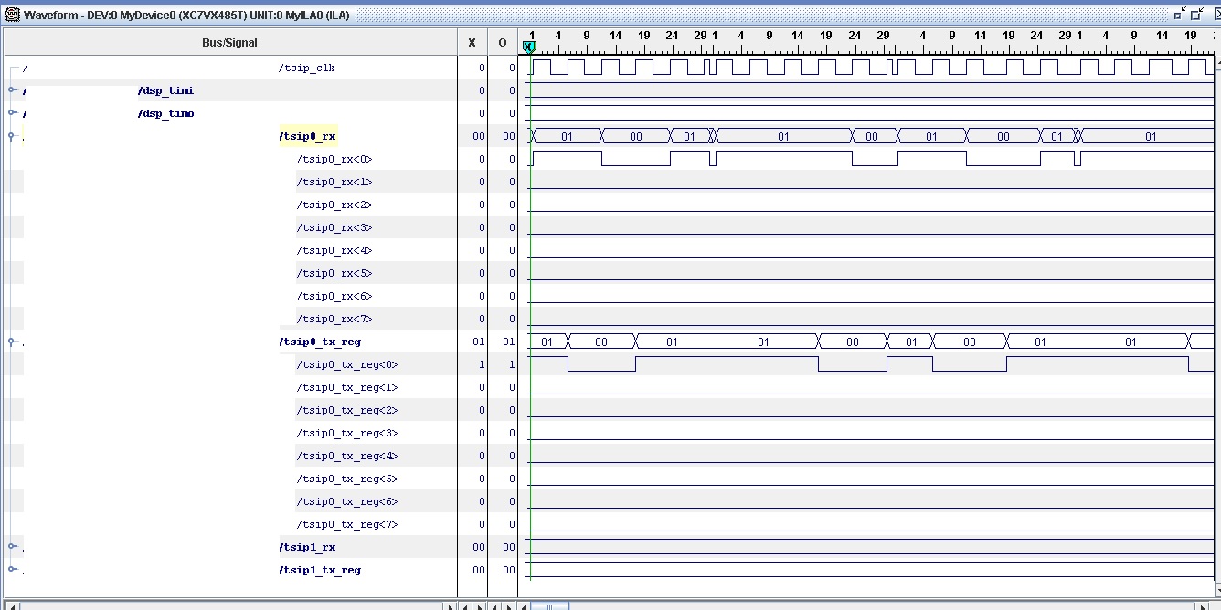
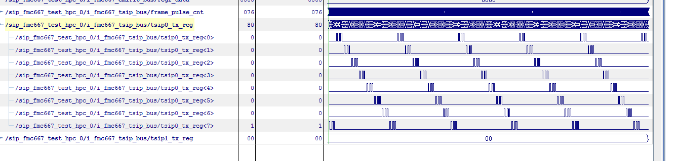
With these settings, I pass the tests on both TSIP ports on the DSP. However, when I scope the TSIP pins on my hardware, I only have one active link on both the TX and RX lines. I would have thought that there would have been 8 active links when I have a 16.384MHz clock and specified a 8.192 Mbps data rate?

Would there be an issue with my frame sync signal? It specifies in the TSIP user guide (SPRUGY4) that for 8.192 Mbps operation, there are 1024 clocks per frame in single-rate clock mode and 2048 clocks per frame in double-rate clock mode, so I presume it should be fine.

I have specified 256 timeslots per frame and considering that each serial interface link supports 8-bit timeslots, does this mean that it is not necessary to operate the other links?

Am I right in thinking that I need to reduce the number of timeslots per frame? If I do, then should I not also need to reduce the frame sync pulse rate?

Regards,

Fearghal

  • Fearghal,

    Since you have data transfer on a single lane I expect the clock and frame sync are acceptable.  What clock mode are you using?  Since the data rate is set to 8.192Mbps and the clock rate is 16.384MHz, I assume you are using the 2x clock mode.  Please provide a scope capture showing the clock, frame pulse and both RX and TX data.  If this is not possible, provide 3 captures: clock and frame pulse, frame pulse and RX data and frame pulse and TX data.

    What is the throughput requirement?  How many timeslots do you need to transport?  TSIP can carry 1024 channels at any of the rates.  At 8.192Mbps you can carry 128 timeslots per lane on 8 lanes.  You can choose to use only the number of lanes required to meet your throughout requirement.

    I expect the problem limiting you to single lane operation is configuration related.  I copied the SW apps team for additional questions.

    Tom


  • Hi Tom,

    I am using double rate clock.

    I can provide an image of data captured using the chipscope tool. I do not have frame sync information in this captured image. Just clock, TX and RX. I will try and update with frame sync included.

    The console output from running the TSIP_testProject for this is as follows:

    [C66xx_0] **************************************************

    ********** TSIP Test Start ***********************
    **************************************************
    Verify TSIP Port 0 data transfer...
    -->Slot 0 verified 808 samples.
    -->Slot 1 verified 808 samples.
    -->Slot 2 verified 808 samples.
    -->Slot 3 verified 808 samples.
    -->Slot 4 verified 808 samples.
    -->Slot 5 verified 808 samples.
    -->Slot 6 verified 808 samples.
    -->Slot 7 verified 808 samples.
    -->Slot 8 verified 808 samples.
    -->Slot 9 verified 808 samples.
    -->Slot 10 verified 808 samples.
    -->Slot 11 verified 808 samples.
    -->Slot 12 verified 808 samples.
    -->Slot 13 verified 808 samples.
    -->Slot 14 verified 808 samples.
    -->Slot 15 verified 808 samples.
    -->Slot 16 verified 808 samples.
    -->Slot 17 verified 808 samples.
    -->Slot 18 verified 808 samples.
    -->Slot 19 verified 808 samples.
    -->Slot 20 verified 808 samples.
    -->Slot 21 verified 808 samples.
    -->Slot 22 verified 808 samples.
    -->Slot 23 verified 808 samples.
    -->Slot 24 verified 808 samples.
    -->Slot 25 verified 808 samples.
    -->Slot 26 verified 808 samples.
    -->Slot 27 verified 808 samples.
    -->Slot 28 verified 808 samples.
    -->Slot 29 verified 808 samples.
    -->Slot 30 verified 808 samples.
    -->Slot 31 verified 808 samples.
    TSIP Port 0 data transfer verfication PASSED
    Verify TSIP Port 1 data transfer...
    -->Slot 0 verified 808 samples.
    -->Slot 1 verified 808 samples.
    -->Slot 2 verified 808 samples.
    -->Slot 3 verified 808 samples.
    -->Slot 4 verified 808 samples.
    -->Slot 5 verified 808 samples.
    -->Slot 6 verified 808 samples.
    -->Slot 7 verified 808 samples.
    -->Slot 8 verified 808 samples.
    -->Slot 9 verified 808 samples.
    -->Slot 10 verified 808 samples.
    -->Slot 11 verified 808 samples.
    -->Slot 12 verified 808 samples.
    -->Slot 13 verified 808 samples.
    -->Slot 14 verified 808 samples.
    -->Slot 15 verified 808 samples.
    -->Slot 16 verified 808 samples.
    -->Slot 17 verified 808 samples.
    -->Slot 18 verified 808 samples.
    -->Slot 19 verified 808 samples.
    -->Slot 20 verified 808 samples.
    -->Slot 21 verified 808 samples.
    -->Slot 22 verified 808 samples.
    -->Slot 23 verified 808 samples.
    -->Slot 24 verified 808 samples.
    -->Slot 25 verified 808 samples.
    -->Slot 26 verified 808 samples.
    -->Slot 27 verified 808 samples.
    -->Slot 28 verified 808 samples.
    -->Slot 29 verified 808 samples.
    -->Slot 30 verified 808 samples.
    -->Slot 31 verified 808 samples.
    TSIP Port 1 data transfer verfication PASSED
    TSIP Test ended. Test Passed.

    I think my issue is with how I send data and how I initialize the application buffers within the TSIP_testProject. I am not sure if I am only sending enough data so that only TSIP TX0 is required?

    Is that what is expected in the TSIP_testProject?

    I know I should have no issue with the TX1-TX7 and RX1-RX7 links, since I can affect these by changing the idle state of the pins. This would leave me to believe that these pins are just not required due to the setup I have.

    What I am looking to do is confirm that all 8 lanes can send and receive data through the provided TSIP_testProject in the C6678 PDK

    Thanks,

    Fearghal

  • Fearghal,

    I would still like to see the requested oscilloscope captures to be able to judge robust timing.  However, I agree with your assessment that the lane use limitation is probably related to the software configuration.

    Tom


  • I have included a pdf of the requested signal timings captured while running the TSIP test project from TI with the settings I have stated above. Is there anything you can suggest with regards to the software configuration that may help me? Would you know if the original test project was only supposed to have one link tested by default?

    Thanks Tom

    Rgds,

    Fearghal

    3343.waveform.pdf

  • Fearghal,

    These are logic analyzer captures.  I need to see oscilloscope captures that clearly show relative timing.

    Tom


  • Fearghal,

    Please provide captures that show the entire frame pulse (i.e. both edges).  Also, for the scope captures, please zoom in to show about 10 clock / data periods.

    Tom


  • Hi Tom,

    I've attached a zip file with the scope captures. Would the Frame Sync and TX/RX images suggest that I am not sending enough information onto the TSIP and so it is not required to have any other links active?

    Considering that changing the idle drive state changes the output on Links 1-7 to either high or low seems to me like I just do not have these links active.

    Rgds,

    Fearghal

    1680.TSIP_SCOPE.zip

  • Fearghal,

    The scope shots show that the frame pulse, clock and data are almost correct.  You stated that you are using the 2X clock mode.  However, the frame pulse is only 1 clock wide.  Idealy it should be 2 clocks wide.  The data bits do appear to be 2 clocks wide.

    How are you looping back the data in the FPGA?  It appears to be a simple bit loopback.  This is not valid.  The TSIP carries data in 8-bit words.  There should be at least an 8-bit delay in the loopback.  Similarly, TSIP transorts channelized data in frame periods.  If you want to loopback data from TX timeslot 0 to RX timeslot 0, the FPGA will need to buffer and delay an entire frame of data.  Assuming you are using all 1024 available timeslots (channels), you will need to buffer 1024 bytes of data.

    I will ask the software support team why they have not responded to your configuration question.

    Tom


  • Hi Tom,

    Thanks for reviewing my signal timings. I will work on the FPGA firmware to try and update the frame sync signal and review how I will pass data within the loopback test.

    Thanks for following up with the software support as well, hopefully someone will recognise if my settings are incorrect.

    Rgds,

    Fearghal

  • Hello Fearghal,

    I had a look at existing TSIP_testProject project and I think it is just using one link.

    In test.h it had definition of numuber of TSIP port used and number of time slots used but no defintion of number of link/lanes being used. Also data buffer is assuming 1 link/lane.

    Another way to verify is after TSIP got configured, looked into Tx or Rx channal bitmap configuration, say: 0x1E08000 to see how many bits were enabled (not 0).

    regards,

    David

  • Hi David,

    I just tested my hardware setup and the channel bitmap configuration registers are all non zero apart from the TSIP0 TX/RX registers.

    Would you have a simple application that I can run that would enable and send data down all TX links? I am struggling to figure out what settings I need to configure to do this. Or could you point me in the direction of what changes I need to make in the current project?

    Thanks,

    Rgds,

    Fearghal

  • Hi David,

    At this point my aim is to be able to transmit data down all 8 TSIP links from the DSP. I have been unable to make further progress on this today and hope you can assist me to adapt the TSIP test project app to enable me to do this?

    I am only defining 32 timeslots (shown in first post) in my tests which would explain the TX and frame sync scope output that I have attached above. I can see that data seems to be sent on the first 512 clock cycles. 512/32 = 16. The clock mode is double data rate so that would indicate that I am sending 32 8 bit packets that are sampled over 2 clock cycles.

    I would like to increase the number of timeslots to the maximum of 1024 that would enable all the TSIP links with the settings I have. However I run into issues where I am unable to set the timeslot number due to restrictions 

    There is a max timeslot (TSIP_MAX_TIMESLOTS) define that is set to 128 (tsip_cfg.h) but the number of timeslots that can be allocated is rstricted to:

    #if ((NUM_USED_TIME_SLOTS * NUM_USED_TSIP_PORTS) > TSIP_MAX_TIMESLOTS )

    Can I simply increase the TSIP_MAX_TIMESLOTS allowed and hence increase the NUM_USED_TIMESLOTS? I tried this previously and ran into errors but would appreciate any feedback you can give me on how I can verify all 8 TSIP TX links on the C6678 DSP.

    Rgds,

    Fearghal

  • Hi again,

    I have updated the following settings to increase the timeslot number size from 128 to 512 timeslots and the number of timeslots used from 32 to 512:

    (test.h)

    /* Size of application buffers */
    #define BUFSIZE_APP 40*2 /*must be a multiple of the tx.frameSize (40).
                                                           Due to L2 memory size, max value for this define is 880*/

    /* Number of TSIP ports used in the test */
    #define NUM_USED_TSIP_PORTS 1

    /* This test uses the same number of time slots per TSIP port being tested*/
    /* Number of used time slots per TSIP port (same for all ports)*/
    #define NUM_USED_TIME_SLOTS 512

    (tsip_cfg.h)

    #define TSIP_MAX_TIMESLOTS       512

    (test.c (highlighted red))

    /************************ GLOBAL VARIABLES ********************/
    /* Define buffers required by TSIP
    Size of buffers depends on the maximal number of timeslots
    to be used. Example below has been updated to 512 timeslots*/

    /* Buffer size is based only on the size of the instance*/
    #define BUFSIZE_TSIP_INST_SHARED 40

    /* Buffer size is function of TSIP_N_PORTS */
    #define BUFSIZE_TSIP_HEAP_SHARED 200

    /* Buffer size is a function of the number of time slots */
    #define BUFSIZE_TSIP_HEAP_TIMESLOT 28672

    /* Buffer size is a function of the number of time slots and TSIP_N_PORTS*/
    #define BUFSIZE_TSIP_TX_DMA_BUFFER 8512

    /* Buffer size is a function of the number of time slots and TSIP_N_PORTS*/
    #define BUFSIZE_TSIP_RX_DMA_BUFFER 8512

    /* Buffer size is based only on the size of the instance*/
    #define BUFSIZE_TSIP_INST_SIZE_PORT 176

    I can see that link 0 is sending data over a full frame, as expected, when the timeslot number is set to 128 or above. However i still have no data sent on any other, even though I expect at least four active links with the timeslot number set to 512. Can anyone explain why I am not seeing data sent on any other link apart from Link 0?

    Regards,

    Fearghal

  • Hello Fearghal,

    I am working on creating an example to use 8 TSIP link/lanes and will provide it roughly within one week.

    regards,

    David

  • Hi David,

    That's great, I have not made any firther progress since so this will be a big help to me. Thank you for the help with this

    Rgds,

    Fearghal

  • Fearghal,

    Looking at the code, only lane 0 is being requested. If you look in the timeslotConfig function within test.c the first few lines of code setup the port ID and the timeslot ID inside the variable “timeSlotLinkPort”. As defined in test_cfg.h, bit 9-11 of this variable is for link number.

     The following code can be added in order to change which lane you want the data to be transmitted/received from: 


     int laneNum = 0; //Choose whichever lane you want, can be 0…7.

    timeSlotLinkPort&=0xFFFFF1FF;

    timeSlotLinkPort|= (laneNum<<9);


    Make sure to add the code right underneath this code:


    timeSlotLinkPort = timeSlot;

    timeSlotLinkPort = TSIP_HAL_SET_BITFIELD (timeSlotLinkPort, tsipPort, TSIP_PORT_MSB, TSIP_PORT_LSB);


    As TSIP is for high speed TDM data, we put the data buffer inside the LL2 for better performance. The TSIP_MAX_TIMESLOTS is defined as 128 in the LLD.

    We ran the test project with different lane numbers in data loopback mode and the test passed. But we don’t have easy way to verify the loopback from an external device (as FPGA in your case). If you can, add the above code into the timeslotConfig function and change the lanes and let us know if data comes out from each respective lane.

    -Dorian

  • Hi Dorian,

    Thanks for your feedback. I will test the TSIP lane selection and will give feedback on the loopback test when I have access to my hardware again in a couple of weeks.

    Rgds,

    Fearghal

  • Dear Dorian,

    I slightly modified our code to map timeslots to given lanes.

    TS0 > Lane 0, TS1 > Lane 1, ..., TS7 > Lane 7, TS8 > Lane 0, TS9 > Lane 1, etc..

    There is some progress as I can see data flowing out on four lanes (0 to 3).

    Then I tried to attach timeslots to Lane 0 to 3, that's fine, data flowing on Lane 0 to 3.

    Then I tried to attach timeslots to Lane 4 to 7, that's fine but data flowing on Lane 0 to 3 and not 4 to 7.

    It is as if out of 3 bits, only 2 lanes bits are used by the driver, can you double check?

    Best Regards,

    Arnaud

  • Okay, some progress:

    CSL_TSIP_DATARATE_16M had to be changed to CSL_TSIP_DATARATE_8M as per this sentence in the user guide (The maximum number of active serial links is reduced to four and two, respectively, in these configurations)

    So we have data on all the eight lanes :)