This thread has been locked.

If you have a related question, please click the "Ask a related question" button in the top right corner. The newly created question will be automatically linked to this question.

Error when Writing to or Reading from UART registers.


Hi,

I am using the C5535 ezdsp, and CCS v4 with Texas Instruments XDS100v2 USB Emulator. 
I am writing code that uses some CSL and some register programming to input an analog audio signal, use the DMA to do processing, and then output UART signals that contain information about the input samples. It seems that when I am debugging and I try to read or write UART registers, or use UART CSL functions that require a handle, I get an error where the device memory bus hangs. 

When i run my code using the debugger, I get an error at the line of code commented below. 


Uint16 register_value;


register_value = UART_PWREMU_MGMT;      // ERROR happens when trying to execute this code 
UART_PWREMU_MGMT = register_value | 0x0000;  


my definition for UART_PWREMU_MGMT is below:


#define UART_PWREMU_MGMT   *(volatile ioport Uint16*)(0x1B18) 


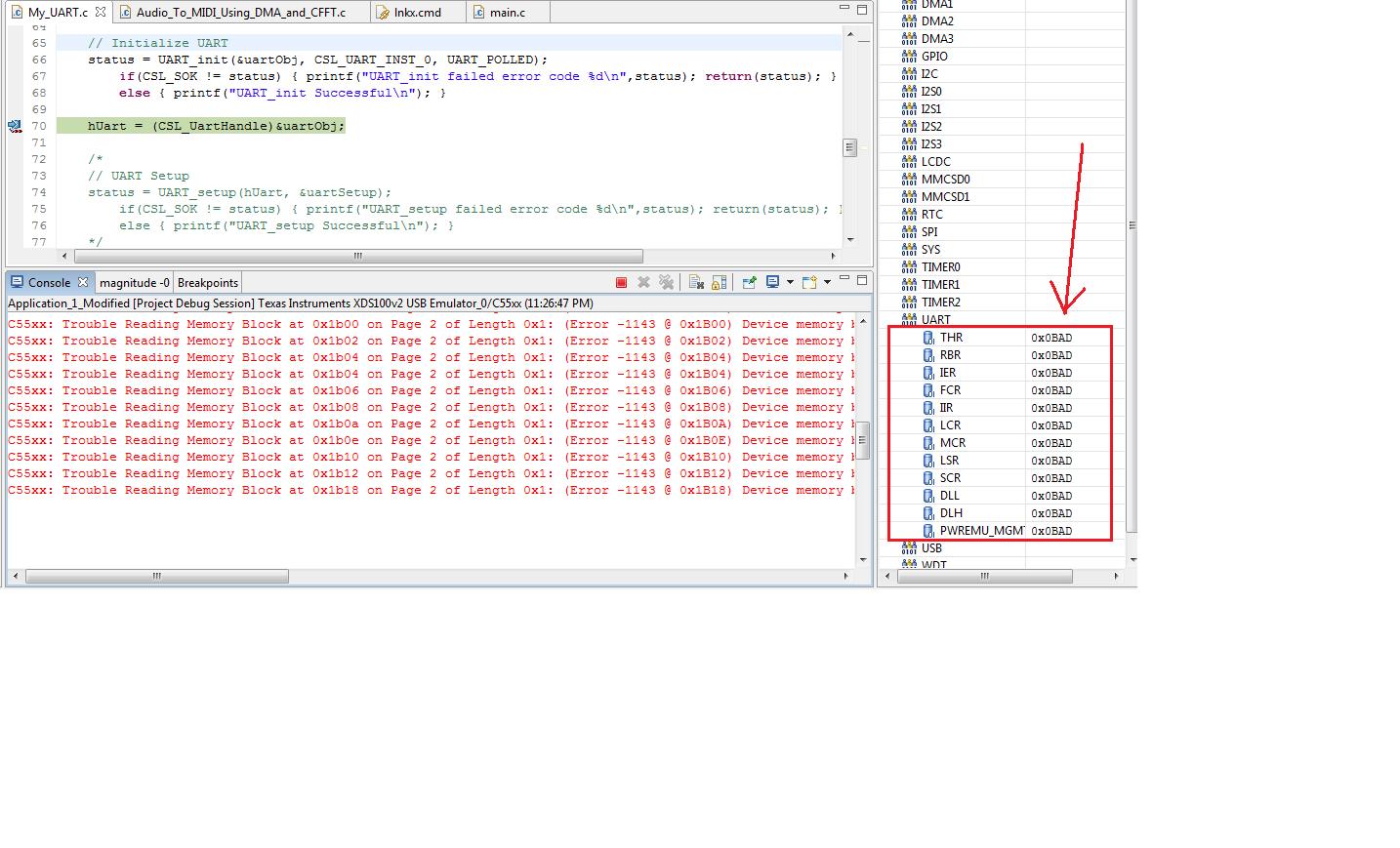
THis is the error I get:


Trouble Reading Memory Block at 0x1b18 on Page 2 of Length 0x1: (Error -1143 @ 0x1B18) Device memory bus has an error and may be hung. Verify that the memory address is in valid memory.

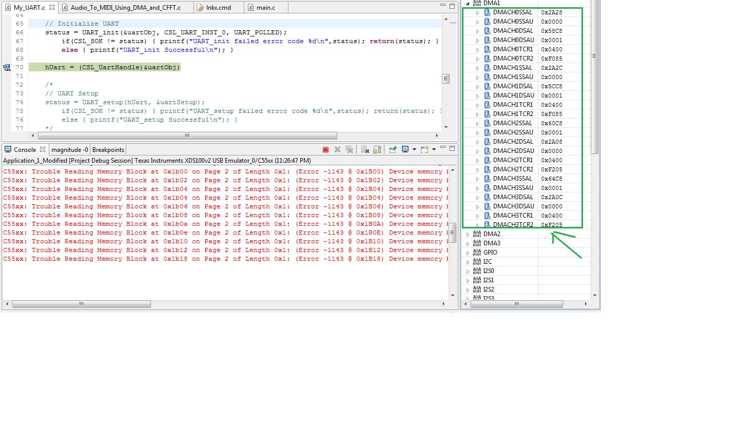
I always get this error when I write to or read from any UART register. If I replace the UART code with code that does anything else, the program runs correctly. I can write to and read from other peripheral registers, but I cannot write to and read from UART registers without receiving this error. I tried using the CSL to configure UART registers, and I get the same error when I use any function that requires a handle, which includes UART_setup, and the  UART_reset function. UART_init (which does not require a handle) can be called successfully. 

If, after receiving this error message, I "Disconnect from the Target", and then try to reconnect, I will get an error that says the "Device memory bus has an error and may be hung.". 

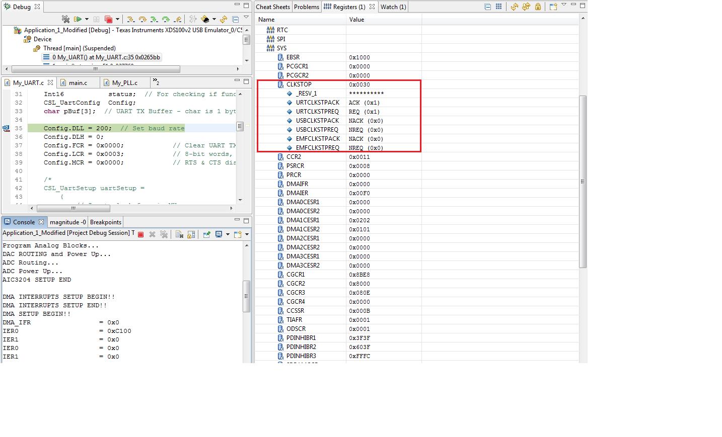
1) I have already made sure that the UART is out of reset by reading from the  PRCR register. 
2) I have also made sure the UART CLK is enabled by writing a 0 to the UARTCG bit in the PCGCR1  register (although the tech ref. says to write a 1 when initializing UART, which I believe is a typo, because a 1 disables the UART CLK).  
3) I have slowed the emulator clock (TCLK) to 100 kHz, which did not fix the problem.
4) I have tried using a different C5535, and the problem persists.  

Why is the debugger having trouble only when reading the memory blocks related to UART? How do I clear this error?

I would greatly appreciate help in resolving this issue. I am attaching my project for reference.

Thanks,

Nate
5125.Application_1_Modified.zip
 

P.S. Does this have anything to do with my problem? I do not know whether I am using port B or A. 


Q: Can I use port B as a UART?
  • A: Yes. The TI XDS100v2 reference design uses the port A of the FTDI2232H to be for JTAG. This leaves the port B available for use either to program the CPLD and/or for use as a UART. The XDS100v2 design puts the CPLD JTAG programming on a selected number of pins (see XDS100v2 readme for details). This allows the CPLD to be programmed via the FTDI device, greatly simplifying manufacturing.
  • Please note that there is a known issue with the current XDS100v2 reference design with the placement of the BCBUS. If you plan to use the port B, please check the readme of the XDS100v2 reference design for details. Generally, a serial port on BCBUS should connect the CPLD as follows: BCBUS1 -> CPLD TCK, BCBUS2 -> CPLD TDI, BCBUS5 -> CPLD TDO, BCBUS6 -> CPLD TMS.
  • Please note that using UART mode simultaneously with Code Composer Studio v4 has NOT been tested on the XDS100v2 design and is not officially supported


  • If you are not using CSL functions, make sure clock for the peripherals you are configuring is enabled properly. Peripheral clocks can be enabled in Peripheral clock gating registers at 0x1c02 and 0x1c03.

    - Pratap.

  • Thanks for the reply  -

    I am using some CSL functions to set up interrupts (the IRQ functions), but I am not using CSL anywhere else.  

    Also, my peripheral clock gating registers 1 and 2 are both set to 0x0000,as they should be - that is not causing the problem. 

    I get this error immediately upon attempting to "step into" any C code that modifies any UART registers. That is the problem. 

    Any other suggestions? 

    Thanks,

    Nathan


  • Update:

    I tried replacing my code with 


    #define UART_DLL   *(volatile ioport Uint16*)(0x1B10)

    int My_UART_Register(void){

    Uint16 register_value;

    register_value = SYS_PCGCR1;
    SYS_PCGCR1 = register_value | 0; // No errors experienced at this point. SYS_PCGCR1 is a system register. 

    UART_DLL = 200; // When trying to step into this line of code I receive the Error quote above!!  


    If I lower the emulator clock (TCLK) to 100 kHz, and I still get this error message at the assignment of UART_DLL:


     Trouble Reading PC Register: (Error -1143 @ 0x0) Device memory bus has an error and may be hung


    Update 2: 

    I tried to check the value of the UART registers in the CCS IDE before i even started adjusting UART register values, and the following is a sample of the errors I get in the console:

    C55xx: Trouble Reading Memory Block at 0x1b00 on Page 2 of Length 0x1: (Error -1143 @ 0x1B00) Device memory bus has an error and may be hung. Verify that the memory address is in valid memory. If error persists, confirm configuration, power-cycle board, and/or try more reliable JTAG settings (e.g. lower TCLK). (Release 5.0.429.0)
    C55xx: Trouble Reading Memory Block at 0x1b02 on Page 2 of Length 0x1: (Error -1143 @ 0x1B02) Device memory bus has an error and may be hung. Verify that the memory address is in valid memory. If error persists, confirm configuration, power-cycle board, and/or try more reliable JTAG settings (e.g. lower TCLK). (Release 5.0.429.0)
    C55xx: Trouble Reading Memory Block at 0x1b04 on Page 2 of Length 0x1: (Error -1143 @ 0x1B04) Device memory bus has an error and may be hung. Verify that the memory address is in valid memory. If error persists, confirm configuration, power-cycle board, and/or try more reliable JTAG settings (e.g. lower TCLK). (Release 5.0.429.0)
    ...
    ... 


    Here is the image trying to read the UART registers, which is unsuccessful:


    Here is my attempt to read the registers for DMA1, which IS successful:


    Basically, the emulator cannot read from any of the UART registers without giving an error, but reading from other registers works fine!!

    Does anyone have any ideas? I am totally baffled. 

    The only thing I can think is that maybe I am not enabling the UART CLK, but I set all peripheral clocks to be enabled by setting:

    // Enable clocks to all peripherals
    SYS_PCGCR1 = 0x0000;
    SYS_PCGCR2 = 0x0000;

    In the Tech Ref. description of the registers, setting a bit to 0 enables the CLK, but in the UART initialization section, the tech ref states that  

    Enable the UART input clock by setting UARTCG to 1 in the peripheral clock gating configuration
    register (PCGCR1).


     Is this a typo?


  • Can you check if UART clock stop requiest is enabled in Peripheral Clock Stop Request/Acknowledge Register at 0x1C3A. Bit 'URTCLKSTPREQ' of this register should be set to '0' to get proper clock for UART block.

    - Pratap.

  • Thanks for the reply Pratap - 

    Hereis a snapshot of my CLKSTOP Register at a break-point that is before I modify any UART registers in my code.  


    The CLKSTOP register value is 0x0030 which means that URTCLKSTPACK and URTCLKSTPREQ are both set to 1.  

    It seems that when I "Reload Program," and my program counter is at the start of "main.c", the CLKSTOP register has already been set to 0x0030. I thought this could mean that the setting of the URTCLKSTPACK and URTCLKSTPREQ bits happens in the GEL file I am using - but I looked at my GEL file and it does not set the bits. I do not know where or why these bits are getting set in the CLKSTOP register. I will try setting them to 0 before I modify any UART registers and report my results here. 

    Thanks!


  • Set the value of 'URTCLKSTPREQ' bit to '0' before configuring UART registers. This will enable access to UART registers.

    - Pratap.

  • Thank you so much Pratap!!!! That worked for me. I do not know where in my code those UART CLKSTOP bits were being set, but adding the following code worked for me:

    Uint16 register_value;

    // Enable clocks to all peripherals
    SYS_PCGCR1 = 0x0000;
    SYS_PCGCR2 = 0x0000;

    // Set the UART CLKSTOP bits to 0 to allow the clock to the UART peripheral.
    register_value = CPU_CLKSTOP;              
    /* I added this line of code, which sets URTCLKSTPACK and URTCLKSTPREQ bits to 0 in order to solve the error */
    CPU_CLKSTOP = register_value & 0xFFCF;