This thread has been locked.

If you have a related question, please click the "Ask a related question" button in the top right corner. The newly created question will be automatically linked to this question.

ZCE BGA Pad Size

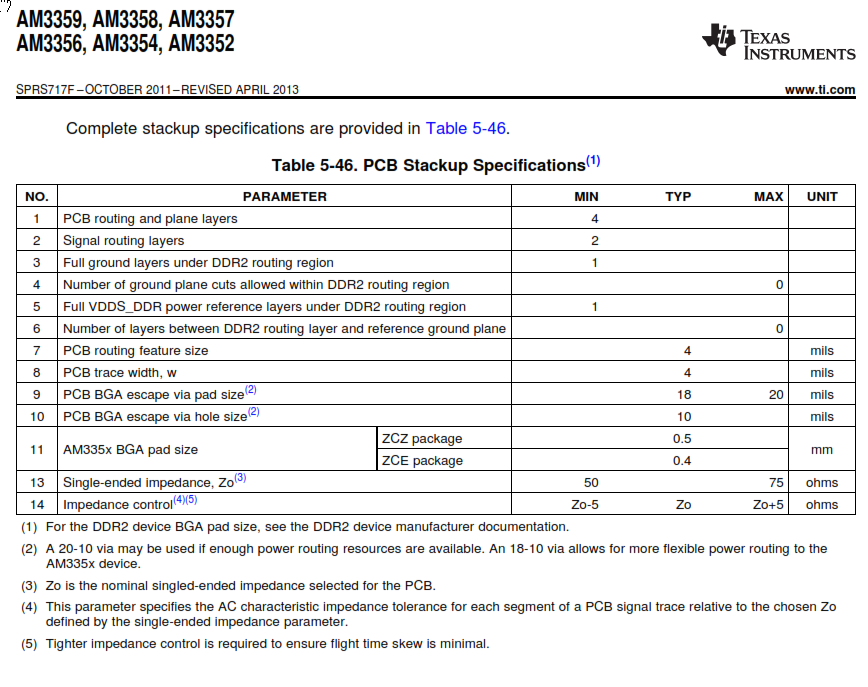
According to the datasheet, the ZCE BGA pad size should be .4mm (15.75mils).  I've downloaded the "am335xevm13x13baseboard_3h0000_1_0A.brd" file. I have the Allegro free file viewer and from what I can measure, the pad is 0.3mm. Can someone please confirm the recommended pad size? The problem is is if the pad size is .4mm and the pitch is .65mm, that only leaves .25mm for routing. As per the datasheet, the trace width is to be .1mm (4mils) with .1mm(4mils) spacing. At this size, the trace won't fit (need .3mm).

  • Hi Matt,
     
    The EVM is built with the ZCZ package. The ZCE package utilizes a technology called "via channel". Here is a document that explains how to route 0.65mm pitch BGA's: http://www.ti.com/lit/an/sprab13a/sprab13a.pdf. Can you tell me whre in the datasheet you have seen the recommended pad size, and from which link did you download the .brd file?
  • The AM335x data sheet only provides mechanical dimensions of the package.  It does not specify the PCB pad size.

    I think you misunderstood the 0,36-0,46 mm dimention on the ZCE package drawing which is the diameter of the solder ball.

    You should discuss pad size with you PCB design, fabrication, and assembly vendors.  In some cases they may want to use SMD pads and other cases they may want to use NSMD pads.

    Regards,
    Paul

  • Thanks to the both of you for your replies. 

    I've copied the portion of the hardware datasheet to which I was referring. It's found on page 162 (and elsewhere) under DDR2 routing. The board layout that has the 0.3mm pad size is "am335xevm13x13baseboard_3h0000_1_0A.brd" from the AM335x_ZCE.zip file downloaded from TI and referenced by, I believe you, Biser, in another post about how to route a "via channel" package.

    I have a call into our PCB house to see what they recommend but it would seem that the 0.3mm size is the largest one could use simply to maintain the 4mil width and spacing minimums. 

  • I think I have found my answer. From the TI website:

    "The IPC has a specification called IPC-7351A.  This specification provides recommendations for all known BGA ball sizes.  Referencing this table will show the optimal ball pad size for any BGA design:

    IPC-7351A for NSMD Pads

    Nominal 

    Ball 

    Diameter*

    Reduction

    Land

    Pattern

    Density Level

    Nominal

    Land

    Diameter

    Land

    Variation

    0.75 25% A 0.55 0.60-0.50
    0.65 25% A 0.50 0.55-0.45
    0.6 25% A 0.45 0.50-0.40
    0.55 25% A 0.40 0.45-0.35
    0.5 20% B 0.40 0.45-0.35
    0.45 20% B 0.35 0.40-0.30
    0.4 20% B 0.30 0.35-0.25
    0.35 20% B 0.30 0.35-0.25
    0.3 20% B 0.25 0.25-0.20
    0.25 20% B 0.20 0.20-0.17
    0.2 15% C 0.17 0.20-0.14
    0.17 15% C 0.15 0.18-0.12
    0.15 15% C 0.13 0.15-0.10
    • Can be found on the TI Mechanical package drawing available in the TI product folder."
    The mechanical drawing lists the ball diameter to approx. .41mm so the appropriate pad diameter is indeed .3mm. The UltraLibrarian translator creates a pad size of .3556mm (at least in Eagle).
    It also mentions on the same page (http://processors.wiki.ti.com/index.php/General_hardware_design/BGA_PCB_design), NSMD is somewhat preferred but the fab house should be consulted.
    One additional question. If, as in the example layout reference earlier, one were to pour patches of copper around groups of ball pads of the same net (for example, DGND), does this now render the pad more like an SMD than an NSMD? If so, does the mask now define the landing pad and should the mask diameter be adjusted to match the .3mm pad?
    Thanks
  • When I sent my previous reply, I did not realize the DDR routing guidelines mentioned pad size.  We are investigating why these values were published in the data sheet.

    The IPC recommendations provide a good starting point.  In most cases your PCB vendor will use these values.

    You need to provide a proper solder mask opening over copper pours or the solder ball may wick away to the copper pour and leave an open-circuit.  The size of this solder mask opening should be discussed with your PCB vendors because there may be specific process dependencies.

    Regards,
    Paul