Dear Members
Q1) According to DM3730 Technical note, I understood that 18-bit Interface can't use look-up table and OSD Function.
12/16/24 bits I/F can use loo-up table.
Is that correct?
What is the function that DM3730 can't support under 18-bit interface conditions? ( as compared to 24bit and 16 bit interface)
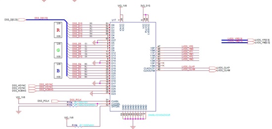
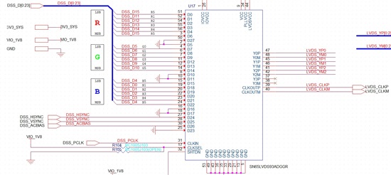
Q2) According to logic-PD as attached ( It is very important for new pcb)
(from attached file )
16-bit SOM Hardware Interface to 18-bit LCD Panel
Before the OS display driver can work, the microprocessor LCD controller must be connected correctly to the LCD color signals. In this example, we connect a 16-bit CPU hardware interface to an 18-bit LCD panel. The advantage of using 16-bit is that the software driver support is already available and does not cause the same loss of performance that may occur when supporting 18-bit display panels due to extra data being fetched across the memory bus. The extra low-order bits for red and blue on the LCD panel are simply driven with copies of the high order bits.
We will use the schematic as attached.
Is that correct?


