This thread has been locked.

If you have a related question, please click the "Ask a related question" button in the top right corner. The newly created question will be automatically linked to this question.

programming registers of a slave IC(LM96570) Using SPI of TMS320C6678 EVM

Other Parts Discussed in Thread: TMS320C6678

Hi,

I am writing programme in CCS  for spi, I facing some problem in getting required output.

This is the my code:

**************************************************

#include <c6x.h>
#include <stdint.h>
#include <evmc66x_spi.h>
#include <stdio.h>
#include <cslr_spi.h>
#include <platform.h>
SPI_STATUS status1, status2;

void main(void) {

while(1){
uint8_t array1[] = {0xAA ,0x55, 0xFF };
uint8_t* ptr1;
ptr1 = &array1[0];
printf("1\n");
status1 =spi_claim(0,10000000);
printf("2\n");
status2 = spi_xfer(0x00000003,0,ptr1,0);
printf("3\n");
spi_release();
printf("4");
}
}

***************************************************

With this code I am expecting array1 data at master o/p pin.


void Osal_platformSpiCsEnter(void)
{
/* Get the hardware semaphore.
*
* Acquire Multi core CPPI synchronization lock
*/
while ((CSL_semAcquireDirect (PLATFORM_SPI_HW_SEM)) == 0);

return;
}

void Osal_platformSpiCsExit (void)
{
/* Release the hardware semaphore
*
* Release multi-core lock.
*/
CSL_semReleaseSemaphore (PLATFORM_SPI_HW_SEM);

return;
}

 I am not understanding here CSL_semAcquireDirect  function unable to return the value 1, means Resource was available and has been allocated to the Master. Can any body what wrong with my code. 

thank you.


regards,

chandu.

  • Chandu,

    I tried your test code (with Osal_platformSpiCsEnter and Osal_platformSpiCsExit in the same source file) on C6678 EVM and could see the Core keeps printing out 1/2/3/4 in while loop. I do not see it is stuck in CSL_semAcquireDirect  function and the Semaphore register shows 0x1 in the memory view. 

    May I ask which platform your are working with and are you using the C6678 platform and CSL libraries please?

  • Hi,

    thank you for your reply. 

    Yes, I am using platform and CSL libraries of version pdk_C6678_1_1_2_5.


    /******************************************************************************
     * Copyright (c) 2011 Texas Instruments Incorporated - http://www.ti.com
     * 
     *  Redistribution and use in source and binary forms, with or without 
     *  modification, are permitted provided that the following conditions 
     *  are met:
     *
     *    Redistributions of source code must retain the above copyright 
     *    notice, this list of conditions and the following disclaimer.
     *
     *    Redistributions in binary form must reproduce the above copyright
     *    notice, this list of conditions and the following disclaimer in the 
     *    documentation and/or other materials provided with the   
     *    distribution.
     *
     *    Neither the name of Texas Instruments Incorporated nor the names of
     *    its contributors may be used to endorse or promote products derived
     *    from this software without specific prior written permission.
     *
     *  THIS SOFTWARE IS PROVIDED BY THE COPYRIGHT HOLDERS AND CONTRIBUTORS 
     *  "AS IS" AND ANY EXPRESS OR IMPLIED WARRANTIES, INCLUDING, BUT NOT 
     *  LIMITED TO, THE IMPLIED WARRANTIES OF MERCHANTABILITY AND FITNESS FOR
     *  A PARTICULAR PURPOSE ARE DISCLAIMED. IN NO EVENT SHALL THE COPYRIGHT 
     *  OWNER OR CONTRIBUTORS BE LIABLE FOR ANY DIRECT, INDIRECT, INCIDENTAL, 
     *  SPECIAL, EXEMPLARY, OR CONSEQUENTIAL DAMAGES (INCLUDING, BUT NOT 
     *  LIMITED TO, PROCUREMENT OF SUBSTITUTE GOODS OR SERVICES; LOSS OF USE,
     *  DATA, OR PROFITS; OR BUSINESS INTERRUPTION) HOWEVER CAUSED AND ON ANY
     *  THEORY OF LIABILITY, WHETHER IN CONTRACT, STRICT LIABILITY, OR TORT 
     *  (INCLUDING NEGLIGENCE OR OTHERWISE) ARISING IN ANY WAY OUT OF THE USE 
     *  OF THIS SOFTWARE, EVEN IF ADVISED OF THE POSSIBILITY OF SUCH DAMAGE.
     * 
     *****************************************************************************/
    
    /******************************************************************************
     *
     * File Name:   evmc66x_spi.c
     *
     * Description: This file implements SPI driver for the NOR flash
     *  
     *****************************************************************************/
     
    /************************
     * Include Files
     ************************/
    #include "platform_internal.h"
    #include <stdio.h>
    
    static uint32_t data1_reg_val;
    
    void spi_delay
    ( 
        uint32_t delay 
    )
    {
        volatile uint32_t i;
    
        for ( i = 0 ; i < delay ; i++ ){ };
    }
    
    
    /******************************************************************************
     * 
     * Function:    spi_claim  
     *
     * Description: This function claims the SPI bus in the SPI controller 
     *
     * Parameters:  Uint32 cs       - Chip Select number for the slave SPI device
     *              Uint32 freq     - SPI clock frequency  
     *
     * Return Value: error status
     * 
     ******************************************************************************/
    SPI_STATUS 
    spi_claim
    (
        uint32_t      cs,
        uint32_t      freq
    )
    {
        uint32_t scalar;
        printf("in spi claim1\n");
        PLIBSPILOCK()
    
        /* Enable the SPI hardware */
        SPI_SPIGCR0 = CSL_SPI_SPIGCR0_RESET_IN_RESET;
    //    spi_delay (2000);
        SPI_SPIGCR0 = CSL_SPI_SPIGCR0_RESET_OUT_OF_RESET;
    
        /* Set master mode, powered up and not activated */
        SPI_SPIGCR1 =   (CSL_SPI_SPIGCR1_MASTER_MASTER << CSL_SPI_SPIGCR1_MASTER_SHIFT)   |
                        (CSL_SPI_SPIGCR1_CLKMOD_INTERNAL << CSL_SPI_SPIGCR1_CLKMOD_SHIFT);
        
        
        /* CS0, CS1, CLK, Slave in and Slave out are functional pins */
        if (cs == 0) {
            SPI_SPIPC0 =    (CSL_SPI_SPIPC0_SCS0FUN0_SPI << CSL_SPI_SPIPC0_SCS0FUN0_SHIFT) |
                            (CSL_SPI_SPIPC0_CLKFUN_SPI << CSL_SPI_SPIPC0_CLKFUN_SHIFT)     |
                            (CSL_SPI_SPIPC0_SIMOFUN_SPI << CSL_SPI_SPIPC0_SIMOFUN_SHIFT)   |
                            (CSL_SPI_SPIPC0_SOMIFUN_SPI << CSL_SPI_SPIPC0_SOMIFUN_SHIFT);
        } else if (cs == 1) {
            SPI_SPIPC0 =    ((CSL_SPI_SPIPC0_SCS0FUN1_SPI << CSL_SPI_SPIPC0_SCS0FUN1_SHIFT) |
                            (CSL_SPI_SPIPC0_CLKFUN_SPI << CSL_SPI_SPIPC0_CLKFUN_SHIFT)     |
                            (CSL_SPI_SPIPC0_SIMOFUN_SPI << CSL_SPI_SPIPC0_SIMOFUN_SHIFT)   |
                            (CSL_SPI_SPIPC0_SOMIFUN_SPI << CSL_SPI_SPIPC0_SOMIFUN_SHIFT)) & 0xFFFF;
        }
        
        /* setup format */
        scalar = ((SPI_MODULE_CLK / freq) - 1 ) & 0xFF;
    
        if ( cs == 0) {
            SPI_SPIFMT0 =   (8 << CSL_SPI_SPIFMT_CHARLEN_SHIFT)               |
                            (scalar << CSL_SPI_SPIFMT_PRESCALE_SHIFT)                      |
                            (CSL_SPI_SPIFMT_PHASE_DELAY << CSL_SPI_SPIFMT_PHASE_SHIFT)     |
                            (CSL_SPI_SPIFMT_POLARITY_LOW << CSL_SPI_SPIFMT_POLARITY_SHIFT) |
                            (CSL_SPI_SPIFMT_SHIFTDIR_MSB << CSL_SPI_SPIFMT_SHIFTDIR_SHIFT);
        }else if ( cs == 1) {
            SPI_SPIFMT0 =   (16 << CSL_SPI_SPIFMT_CHARLEN_SHIFT)               |
                            (scalar << CSL_SPI_SPIFMT_PRESCALE_SHIFT)                      |
                            (CSL_SPI_SPIFMT_PHASE_NO_DELAY << CSL_SPI_SPIFMT_PHASE_SHIFT)     |
                            (CSL_SPI_SPIFMT_POLARITY_LOW << CSL_SPI_SPIFMT_POLARITY_SHIFT) |
                            (CSL_SPI_SPIFMT_SHIFTDIR_MSB << CSL_SPI_SPIFMT_SHIFTDIR_SHIFT);
        }
        
        /* hold cs active at end of transfer until explicitly de-asserted */
        data1_reg_val = (CSL_SPI_SPIDAT1_CSHOLD_ENABLE << CSL_SPI_SPIDAT1_CSHOLD_SHIFT) |
                        (0x02 << CSL_SPI_SPIDAT1_CSNR_SHIFT);
         if (cs == 0) {
             SPI_SPIDAT1 =   (CSL_SPI_SPIDAT1_CSHOLD_ENABLE << CSL_SPI_SPIDAT1_CSHOLD_SHIFT) |
                             (0x02 << CSL_SPI_SPIDAT1_CSNR_SHIFT);
         } 
    
        /* including a minor delay. No science here. Should be good even with
        * no delay
        */
        if (cs == 0) {
            SPI_SPIDELAY =  (8 << CSL_SPI_SPIDELAY_C2TDELAY_SHIFT) |
                            (8 << CSL_SPI_SPIDELAY_T2CDELAY_SHIFT);
            /* default chip select register */
            SPI_SPIDEF  = CSL_SPI_SPIDEF_RESETVAL;        
        } else if (cs == 1) {    
            SPI_SPIDELAY =  (6 << CSL_SPI_SPIDELAY_C2TDELAY_SHIFT) |
                            (3 << CSL_SPI_SPIDELAY_T2CDELAY_SHIFT);
        }
        
        /* no interrupts */
        SPI_SPIINT0 = CSL_SPI_SPIINT0_RESETVAL;
        SPI_SPILVL  = CSL_SPI_SPILVL_RESETVAL;
    
        /* enable SPI */
        SPI_SPIGCR1 |= ( CSL_SPI_SPIGCR1_ENABLE_ENABLE << CSL_SPI_SPIGCR1_ENABLE_SHIFT );
    
        if (cs == 1) {
            SPI_SPIDAT0 = 1 << 15; 
            spi_delay (10000);        
            /* Read SPIFLG, wait untill the RX full interrupt */
            if ( (SPI_SPIFLG & (CSL_SPI_SPIFLG_RXINTFLG_FULL<<CSL_SPI_SPIFLG_RXINTFLG_SHIFT)) ) {                
                /* Read one byte data */
                scalar = SPI_SPIBUF & 0xFF;
                /* Clear the Data */
                SPI_SPIBUF = 0;
            }
            else {
                /* Read one byte data */
                scalar = SPI_SPIBUF & 0xFF;
                return SPI_EFAIL;
            }
        }
        printf("in spi claim2\n");
        return SPI_EOK;
    
    }
    
    /******************************************************************************
     * 
     * Function:    spi_release  
     *
     * Description: This function releases the bus in SPI controller 
     *
     * Parameters:  None
     *
     * Return Value: None
     * 
     ******************************************************************************/
    void 
    spi_release
    (
        void
    )
    {
        /* Disable the SPI hardware */
    	printf("in spi release1\n");
        SPI_SPIGCR1 = CSL_SPI_SPIGCR1_RESETVAL;
    
        PLIBSPIRELEASE()
        printf("in spi release2\n");
    }
    
    /******************************************************************************
     * 
     * Function:    spi_xfer  
     *
     * Description: This function sends and receives 8-bit data serially
     *
     * Parameters:  uint32_t nbytes   - Number of bytes of the TX data
     *              uint8_t* data_out - Pointer to the TX data
     *              uint8_t* data_in  - Pointer to the RX data
     *              Bool terminate  - TRUE: terminate the transfer, release the CS
     *                                FALSE: hold the CS
     *
     * Return Value: error status
     * 
     ******************************************************************************/
    SPI_STATUS 
    spi_xfer
    (
        uint32_t              nbytes,
        uint8_t*              data_out,
        uint8_t*              data_in,
        Bool                terminate
    )
    {
        uint32_t          i, buf_reg;
        uint8_t*          tx_ptr = data_out;
        uint8_t*          rx_ptr = data_in;
        
        
        /* Clear out any pending read data */
        SPI_SPIBUF;
        printf("in spi xfer1\n");
        for (i = 0; i < nbytes; i++) 
        {
            /* Wait untill TX buffer is not full */
            while( SPI_SPIBUF & CSL_SPI_SPIBUF_TXFULL_MASK );
            
            /* Set the TX data to SPIDAT1 */
            data1_reg_val &= ~0xFFFF;
            if(tx_ptr) 
            {
                data1_reg_val |= *tx_ptr & 0xFF;
                tx_ptr++;
            }
            
            /* Write to SPIDAT1 */
            if((i == (nbytes -1)) && (terminate)) 
            {
                /* Release the CS at the end of the transfer when terminate flag is TRUE */
                SPI_SPIDAT1 = data1_reg_val & ~(CSL_SPI_SPIDAT1_CSHOLD_ENABLE << CSL_SPI_SPIDAT1_CSHOLD_SHIFT);
            } else 
            {
                SPI_SPIDAT1 = data1_reg_val;
            }
            
            
            /* Read SPIBUF, wait untill the RX buffer is not empty */
            while ( SPI_SPIBUF & ( CSL_SPI_SPIBUF_RXEMPTY_MASK ) );
            
            /* Read one byte data */
            buf_reg = SPI_SPIBUF;
            if(rx_ptr) 
            {
                *rx_ptr = buf_reg & 0xFF;
                rx_ptr++;
            }
        }
        printf("in spi xfer2\n");
        return SPI_EOK;
        
    }
    
    
    /******************************************************************************
     * 
     * Function:    spi_cmd  
     *
     * Description: This function sends a single byte command and receives response data
     *
     * Parameters:  uint8_t  cmd      - Command sent to the NOR flash
     *              uint8_t* response - Pointer to the RX response data
     *              uint32_t len      - Lenght of the response in bytes
     *
     * Return Value: error status
     * 
     ******************************************************************************/
    SPI_STATUS 
    spi_cmd
    (
        uint8_t               cmd,
        uint8_t*              response,
        uint32_t              len
    )
    {
        Bool        flags = FALSE;
        uint32_t      ret;
        
        if (len == 0)
        {
            flags = TRUE;
        }
        
        /* Send the command byte */
        ret = spi_xfer(1, &cmd, NULL, flags);
        if (ret) 
        {
        	IFPRINT (platform_write("SF: Failed to send command %02x: %d\n", cmd, ret));
            return ret;
        }
        
        /* Receive the response */
        if (len) 
        {
            ret = spi_xfer(len, NULL, response, TRUE);
            if (ret)
            {
            	IFPRINT (platform_write("SF: Failed to read response (%zu bytes): %d\n",  len, ret));
            }
        }
        
        return ret;
    }
    
    /******************************************************************************
     * 
     * Function:    spi_cmd_read  
     *
     * Description: This function sends a read command and reads data from the flash
     *
     * Parameters:  uint8_t  cmd      - Command sent to the NOR flash
     *              uint32_t cmd_len  - Length of the command in bytes
     *              uint8_t* dat      - Pointer to the data read
     *              uint32_t data_len - Lenght of the data read in bytes
     *
     * Return Value: error status
     * 
     ******************************************************************************/
    SPI_STATUS 
    spi_cmd_read
    (
        uint8_t*              cmd,
        uint32_t              cmd_len,
        uint8_t*              data,
        uint32_t              data_len
    )
    {
        Bool        flags = FALSE;
        uint32_t      ret;
        
        if (data_len == 0)
        {
            flags = TRUE;
        }
    
        /* Send read command */
        ret = spi_xfer(cmd_len, cmd, NULL, flags);
        if (ret) 
        {
        	IFPRINT (platform_write("SF: Failed to send read command (%zu bytes): %d\n",
                   cmd_len, ret));
        } 
        else if (data_len != 0) 
        {
            /* Read data */
            ret = spi_xfer(data_len, NULL, data, TRUE);
            if (ret)
            {
            	IFPRINT (platform_write("SF: Failed to read %zu bytes of data: %d\n",
                       data_len, ret));
            }
        }
        
        return ret;
    }
    
    /******************************************************************************
     * 
     * Function:    spi_cmd_write  
     *
     * Description: This function sends a write command and writes data to the flash
     *
     * Parameters:  uint8_t  cmd      - Command sent to the NOR flash
     *              uint32_t cmd_len  - Length of the command in bytes
     *              uint8_t* dat      - Pointer to the data to be written
     *              uint32_t data_len - Lenght of the data in bytes
     *
     * Return Value: error status
     * 
     ******************************************************************************/
    SPI_STATUS 
    spi_cmd_write
    (
        uint8_t*        cmd,
        uint32_t        cmd_len,
        uint8_t*        data,
        uint32_t        data_len
    )
    {
        Bool           flags = FALSE;
        uint32_t         ret;
        
        if (data_len == 0)
        {
            flags = TRUE;
        }
        
        /* Send write command */
        ret = spi_xfer(cmd_len, cmd, NULL, flags);
        if (ret) 
        {
        	IFPRINT (platform_write("SF: Failed to send write command (%zu bytes): %d\n",
                cmd_len, ret));
        } 
        else if (data_len != 0) 
        {
            /* Write data */
            ret = spi_xfer(data_len, data, NULL, TRUE);
            if (ret)
            {
            	IFPRINT (platform_write("SF: Failed to write %zu bytes of data: %d\n",
                data_len, ret));
            }
        }
        
        return ret;
    }
    
    
    /******************************************************************************
     * 
     * Function:    spi_read_word  
     *
     * Description: This function sends a read command and reads data in 16-bit data format  
     *
     * Parameters:  uint16_t* cmd_buf  - Pointer to the command sent
     *              uint32_t cmd_len   - Length of the command in words
     *              uint16_t* data_buf - Pointer to the data read
     *              uint32_t data_len  - Lenght of the data read in words
     *
     * Return Value: error status
     * 
     ******************************************************************************/
    SPI_STATUS 
    spi_read_word
    (
        uint16_t*             cmd_buf,
        uint32_t              cmd_len,
        uint16_t*             data_buf,
        uint32_t              data_len
    )
    {
        uint32_t          data1_reg;
        uint16_t*         tx_ptr = cmd_buf;
        uint16_t*         rx_ptr = data_buf;
        
    	/* disable the SPI communication by setting 
    	 * the SPIGCR1.ENABLE to 0 
    	 * 
    	 * 
    	 * SPIGCR1
    	 * ============================================
    	 * Bit 	Field 	Value 		Description
    	 * 24 	ENABLE 	0			SPI disable
    	 * ============================================
    	 */
    	data1_reg = 0x1 << 24;
    	data1_reg = ~data1_reg;
        SPI_SPIGCR1 &= data1_reg;
    
    	/*
    	 * clean TX data into SPIDAT0
    	 * 
    	 * SPIDAT0
    	 * ============================================
    	 * Bit 	Field 	Value 		Description
    	 * 15-0 TXDATA 	0-FFFFh 	SPI transmit data
    	 * ============================================
    	 * 
    	 */
    
        SPI_SPIDAT0 = 0;
    
    	/* 8.
    	 * Enable the SPI communication by setting 
    	 * the SPIGCR1.ENABLE to 1 
    	 * 
    	 * 
    	 * SPIGCR1
    	 * ============================================
    	 * Bit 	Field 	Value 		Description
    	 * 24 	ENABLE 	1			SPI enable
    	 * ============================================
    	 */
    
    	data1_reg = 0x1 << 24;
        SPI_SPIGCR1 = (SPI_SPIGCR1 | data1_reg);    
        
        {
            {
                SPI_SPIDAT0 = *tx_ptr;
                spi_delay(10000);
            }
    
            /* Read SPIFLG, wait untill the RX full interrupt */
            if ( (SPI_SPIFLG & (CSL_SPI_SPIFLG_RXINTFLG_FULL<<CSL_SPI_SPIFLG_RXINTFLG_SHIFT)) ) {                
                /* Read one byte data */
                *rx_ptr = SPI_SPIBUF & 0xFF;
                SPI_SPIBUF = 0;
            }
            else {
                return SPI_EFAIL;
            }
            
        }
        
        return SPI_EOK;
    
    }
    
    /******************************************************************************
     * 
     * Function:    spi_write_word  
     *
     * Description: This function sends a write command and writes data in 16-bit data format 
     *
     * Parameters:  uint16_t* cmd_buf  - Pointer to the command sent
     *              uint32_t cmd_len   - Length of the command in bytes
     *              uint16_t* data_buf - Pointer to the data read
     *              uint32_t data_len  - Lenght of the data read in bytes
     *
     * Return Value: error status
     * 
     ******************************************************************************/
    SPI_STATUS 
    spi_write_word
    (
        uint16_t*             cmd_buf,
        uint32_t              cmd_len,
        uint16_t*             data_buf,
        uint32_t              data_len
    )
    {
        uint32_t          data1_reg;
        uint16_t*         tx_ptr = cmd_buf;
    
    	/* disable the SPI communication by setting 
    	 * the SPIGCR1.ENABLE to 0 
    	 * 
    	 * 
    	 * SPIGCR1
    	 * ============================================
    	 * Bit 	Field 	Value 		Description
    	 * 24 	ENABLE 	0			SPI disable
    	 * ============================================
    	 */
    	data1_reg = 0x1 << 24;
    	data1_reg = ~data1_reg;
        SPI_SPIGCR1 &= data1_reg;
    
    	/*
    	 * clean TX data into SPIDAT0
    	 * 
    	 * SPIDAT0
    	 * ============================================
    	 * Bit 	Field 	Value 		Description
    	 * 15-0 TXDATA 	0-FFFFh 	SPI transmit data
    	 * ============================================
    	 * 
    	 */
    
        SPI_SPIDAT0 = 0;
    
    	/* 8.
    	 * Enable the SPI communication by setting 
    	 * the SPIGCR1.ENABLE to 1 
    	 * 
    	 * 
    	 * SPIGCR1
    	 * ============================================
    	 * Bit 	Field 	Value 		Description
    	 * 24 	ENABLE 	1			SPI enable
    	 * ============================================
    	 */
    
    	data1_reg = 0x1 << 24;
        SPI_SPIGCR1 = (SPI_SPIGCR1 | data1_reg);    
        
        {
            {
                SPI_SPIDAT0 = *tx_ptr;
                spi_delay(10000);
            }
    
            /* Read SPIFLG, wait untill the RX full interrupt */
            if ( (SPI_SPIFLG & (CSL_SPI_SPIFLG_TXINTFLG_EMPTY<<CSL_SPI_SPIFLG_TXINTFLG_SHIFT)) ) {                
                /* Clear the SPIBUF */
                SPI_SPIBUF = 0;
                return SPI_EOK;
            }
            else {
                return SPI_EFAIL;
            }
            
        }
    }


    I dont know what correction I  made now I am also could get 1/2/3/4 in console. but array1 data in my code  was not  observed  in oscilloscope at the master output pin, and clock pin showing just 1.8v. 

    And 

    ************************************************************

    void Osal_platformSpiCsEnter(void)
    {
    /* Get the hardware semaphore.
    *
    * Acquire Multi core CPPI synchronization lock
    */
    while ((CSL_semAcquireDirect (PLATFORM_SPI_HW_SEM)) == 0);

    return;
    }

    CSL_IDEF_INLINE Uint8 CSL_semAcquireDirect (Uint8 semNum)
    {
    /* Direct Access Request: Read from the SEMn register */
    printf("in CSL_semAcquireDirect1\n");
    return CSL_FEXT (hSEM->SEM[semNum], SEM_SEM_FREE);
    }

    ************************************************************

    Here PLATFORM_SPI_HW_SEM=3, if it is passed to CSL_semAcquireDirect then what refers to hSEM->SEM[semNum], which field in SEM register indicates the resource allocation and why  this PLATFORM_SPI_HW_SEM=3. Please can you make understand these things. Can you please tell me the description of register SEM[0-99][100-114].

    thank you,

    regards,

    chandu.

  • Chandu,

    1. The clock domain of SPI is under software control and we need to enable the domain in PSC in order to use it.

    So do you have the code in your test to enable SPI clock domain such as the follows in "evmc6678.c" file?

    CSL_PSC_setModuleNextState (CSL_PSC_LPSC_EMIF25_SPI,  PSC_MODSTATE_ENABLE);

    2. There are 32 semaphores available in C6678 as mentioned in data manual. I think "PLATFORM_SPI_HW_SEM=3" is just one parameter chosen by the platform example to demonstrate. "cslr_sem.h" shows hSEM->SEM is for the Direct Register. Please refer to Semaphore user guide below for the detailed descriptions of Direct Register, such as section 3.1 and 10.4:

    http://www.ti.com/lit/ug/sprugs3a/sprugs3a.pdf


  • Hi,

    Thank you for your favourable help.

        I am not understanding how to use the CSL_PSC_setModuleNextState(CSL_PSC_LPSC_EMIF25_SPI,  PSC_MODSTATE_ENABLE);  from evmc6678.c.

    I tried to enable the module clock using the PowerUpDomains function defined in evmc6678.c .  c code given below.

    *************************************************

    #include <c6x.h>
    #include <stdint.h>
    #include <evmc66x_spi.h>
    #include <stdio.h>
    #include <cslr_spi.h>
    #include <platform.h>
    #include "platform_internal.h"
    SPI_STATUS status1, status2;

    void main(void) {

    PowerUpDomains();    // enable module clock 
    while(1){

    uint8_t array1[] = {0xAA ,0x55, 0xFF};
    uint8_t* ptr1;
    ptr1 = &array1[0];
    printf("1\n");
    status1 =spi_claim(0,10000000);
    printf("2\n");
    status2 = spi_xfer(0x00000003,0,ptr1,0);
    printf("3\n");
    spi_release();
    printf("4\n");
    }

    }

    *************************************************

                 But still could not observing  clock and array1 data at clock pin and master pin of SPI. When you tried my code did you observed  the SIMO and clock pins?

     If possible please help with code to get the 3 byte data at the master pin with respect to clock. Please help me sir, it is very useful to my work.

    thank you. 

    regards,

    chandu.

  • Chandu,

    Please refer to the "spi_xfer" inputs in "evmc66x_spi.c" file. In order to observe the data out on pin SIMO, please update the code as follows:

    //status2 = spi_xfer(0x00000003,0,ptr1,0);
    status2 = spi_xfer(0x00000003,ptr1,0,0);

    And you should be able to observe the SPI_CLK and SPI_SIMO activity on the Expansion Header (TEST_PH1) on EVM when you run the test case. Please refer to the EVM Technial Referenced Manual for the pinout, such as pin 69 is SPI_CLK and pin 65 is SPI_SIMO in TEST_PH1 of EVM6678L/LE Rev1.0.

  • Hi,

    Thanks for your reply.

     I am very sorry that asking again about my problem. 

    yes sir your right, I did the correction in my code that your mentioned in the last post. But still I am not getting my array data and clock  at pins 69,65 in expansion header.

    So please help me sir, it is very useful for me.

    thank you very much.

    regards,

    chandu.


  • Chandu,

    I did the testing on EVM6678L/LE Rev1.0, which EVM reversion are you using please?

    And did you have the while loop to keep pushing the data and clock please?

    And what are you observed on pin 65 and 69 please? Any difference when you stop running the test case?


  • Hi,

    thanks for your reply.

     I am working on TMDXEVM6678L EVM Version 2.0.

    *************************************************

    #include <c6x.h>
    #include <stdint.h>
    #include <evmc66x_spi.h>
    #include <stdio.h>
    #include <cslr_spi.h>
    #include <platform.h>
    #include "platform_internal.h"
    SPI_STATUS status1, status2;

    void main(void) {

    PowerUpDomains();    // enable module clock 
    while(1){

    uint8_t array1[] = {0xAA ,0x55, 0xFF};
    uint8_t* ptr1;
    ptr1 = &array1[0];
    printf("1\n");
    status1 =spi_claim(0,10000000);
    printf("2\n");
    status2 = spi_xfer(0x00000003,0,ptr1,0);
    printf("3\n");
    spi_release();
    printf("4\n");
    }

    }

    *************************************************

    above is the my ccs version 5.2.1.00018 code. 

    Yes sir, I am using while loop as shown  to keep on push data.

    When I loaded the evm with .out file, on resume cpu getting into while(1){ --- } .And no expected output at the pins 63,65,67,69.

    MISO (63)= MOSI (65)=clk(69)= some milli volts. but at CS1(67)=1.8 v.

    the spi_claim,spi_xfer,spi_release function definitions are given by this .c file.

    /******************************************************************************
     * Copyright (c) 2011 Texas Instruments Incorporated - http://www.ti.com
     * 
     *  Redistribution and use in source and binary forms, with or without 
     *  modification, are permitted provided that the following conditions 
     *  are met:
     *
     *    Redistributions of source code must retain the above copyright 
     *    notice, this list of conditions and the following disclaimer.
     *
     *    Redistributions in binary form must reproduce the above copyright
     *    notice, this list of conditions and the following disclaimer in the 
     *    documentation and/or other materials provided with the   
     *    distribution.
     *
     *    Neither the name of Texas Instruments Incorporated nor the names of
     *    its contributors may be used to endorse or promote products derived
     *    from this software without specific prior written permission.
     *
     *  THIS SOFTWARE IS PROVIDED BY THE COPYRIGHT HOLDERS AND CONTRIBUTORS 
     *  "AS IS" AND ANY EXPRESS OR IMPLIED WARRANTIES, INCLUDING, BUT NOT 
     *  LIMITED TO, THE IMPLIED WARRANTIES OF MERCHANTABILITY AND FITNESS FOR
     *  A PARTICULAR PURPOSE ARE DISCLAIMED. IN NO EVENT SHALL THE COPYRIGHT 
     *  OWNER OR CONTRIBUTORS BE LIABLE FOR ANY DIRECT, INDIRECT, INCIDENTAL, 
     *  SPECIAL, EXEMPLARY, OR CONSEQUENTIAL DAMAGES (INCLUDING, BUT NOT 
     *  LIMITED TO, PROCUREMENT OF SUBSTITUTE GOODS OR SERVICES; LOSS OF USE,
     *  DATA, OR PROFITS; OR BUSINESS INTERRUPTION) HOWEVER CAUSED AND ON ANY
     *  THEORY OF LIABILITY, WHETHER IN CONTRACT, STRICT LIABILITY, OR TORT 
     *  (INCLUDING NEGLIGENCE OR OTHERWISE) ARISING IN ANY WAY OUT OF THE USE 
     *  OF THIS SOFTWARE, EVEN IF ADVISED OF THE POSSIBILITY OF SUCH DAMAGE.
     * 
     *****************************************************************************/
    
    /******************************************************************************
     *
     * File Name:   evmc66x_spi.c
     *
     * Description: This file implements SPI driver for the NOR flash
     *  
     *****************************************************************************/
     
    /************************
     * Include Files
     ************************/
    #include "platform_internal.h"
    #include <stdio.h>
    
    static uint32_t data1_reg_val;
    
    void spi_delay
    ( 
        uint32_t delay 
    )
    {
        volatile uint32_t i;
    
        for ( i = 0 ; i < delay ; i++ ){ };
    }
    
    
    /******************************************************************************
     * 
     * Function:    spi_claim  
     *
     * Description: This function claims the SPI bus in the SPI controller 
     *
     * Parameters:  Uint32 cs       - Chip Select number for the slave SPI device
     *              Uint32 freq     - SPI clock frequency  
     *
     * Return Value: error status
     * 
     ******************************************************************************/
    SPI_STATUS 
    spi_claim
    (
        uint32_t      cs,
        uint32_t      freq
    )
    {
        uint32_t scalar;
        printf("in spi claim1\n");
        PLIBSPILOCK()
    
        /* Enable the SPI hardware */
        SPI_SPIGCR0 = CSL_SPI_SPIGCR0_RESET_IN_RESET;
    //    spi_delay (2000);
        SPI_SPIGCR0 = CSL_SPI_SPIGCR0_RESET_OUT_OF_RESET;
    
        /* Set master mode, powered up and not activated */
        SPI_SPIGCR1 =   (CSL_SPI_SPIGCR1_MASTER_MASTER << CSL_SPI_SPIGCR1_MASTER_SHIFT)   |
                        (CSL_SPI_SPIGCR1_CLKMOD_INTERNAL << CSL_SPI_SPIGCR1_CLKMOD_SHIFT);
        
        
        /* CS0, CS1, CLK, Slave in and Slave out are functional pins */
        if (cs == 0) {
            SPI_SPIPC0 =    (CSL_SPI_SPIPC0_SCS0FUN0_SPI << CSL_SPI_SPIPC0_SCS0FUN0_SHIFT) |
                            (CSL_SPI_SPIPC0_CLKFUN_SPI << CSL_SPI_SPIPC0_CLKFUN_SHIFT)     |
                            (CSL_SPI_SPIPC0_SIMOFUN_SPI << CSL_SPI_SPIPC0_SIMOFUN_SHIFT)   |
                            (CSL_SPI_SPIPC0_SOMIFUN_SPI << CSL_SPI_SPIPC0_SOMIFUN_SHIFT);
        } else if (cs == 1) {
            SPI_SPIPC0 =    ((CSL_SPI_SPIPC0_SCS0FUN1_SPI << CSL_SPI_SPIPC0_SCS0FUN1_SHIFT) |
                            (CSL_SPI_SPIPC0_CLKFUN_SPI << CSL_SPI_SPIPC0_CLKFUN_SHIFT)     |
                            (CSL_SPI_SPIPC0_SIMOFUN_SPI << CSL_SPI_SPIPC0_SIMOFUN_SHIFT)   |
                            (CSL_SPI_SPIPC0_SOMIFUN_SPI << CSL_SPI_SPIPC0_SOMIFUN_SHIFT)) & 0xFFFF;
        }
        
        /* setup format */
        scalar = ((SPI_MODULE_CLK / freq) - 1 ) & 0xFF;
    
        if ( cs == 0) {
            SPI_SPIFMT0 =   (8 << CSL_SPI_SPIFMT_CHARLEN_SHIFT)               |
                            (scalar << CSL_SPI_SPIFMT_PRESCALE_SHIFT)                      |
                            (CSL_SPI_SPIFMT_PHASE_DELAY << CSL_SPI_SPIFMT_PHASE_SHIFT)     |
                            (CSL_SPI_SPIFMT_POLARITY_LOW << CSL_SPI_SPIFMT_POLARITY_SHIFT) |
                            (CSL_SPI_SPIFMT_SHIFTDIR_MSB << CSL_SPI_SPIFMT_SHIFTDIR_SHIFT);
        }else if ( cs == 1) {
            SPI_SPIFMT0 =   (16 << CSL_SPI_SPIFMT_CHARLEN_SHIFT)               |
                            (scalar << CSL_SPI_SPIFMT_PRESCALE_SHIFT)                      |
                            (CSL_SPI_SPIFMT_PHASE_NO_DELAY << CSL_SPI_SPIFMT_PHASE_SHIFT)     |
                            (CSL_SPI_SPIFMT_POLARITY_LOW << CSL_SPI_SPIFMT_POLARITY_SHIFT) |
                            (CSL_SPI_SPIFMT_SHIFTDIR_MSB << CSL_SPI_SPIFMT_SHIFTDIR_SHIFT);
        }
        
        /* hold cs active at end of transfer until explicitly de-asserted */
        data1_reg_val = (CSL_SPI_SPIDAT1_CSHOLD_ENABLE << CSL_SPI_SPIDAT1_CSHOLD_SHIFT) |
                        (0x02 << CSL_SPI_SPIDAT1_CSNR_SHIFT);
         if (cs == 0) {
             SPI_SPIDAT1 =   (CSL_SPI_SPIDAT1_CSHOLD_ENABLE << CSL_SPI_SPIDAT1_CSHOLD_SHIFT) |
                             (0x02 << CSL_SPI_SPIDAT1_CSNR_SHIFT);
         } 
    
        /* including a minor delay. No science here. Should be good even with
        * no delay
        */
        if (cs == 0) {
            SPI_SPIDELAY =  (8 << CSL_SPI_SPIDELAY_C2TDELAY_SHIFT) |
                            (8 << CSL_SPI_SPIDELAY_T2CDELAY_SHIFT);
            /* default chip select register */
            SPI_SPIDEF  = CSL_SPI_SPIDEF_RESETVAL;        
        } else if (cs == 1) {    
            SPI_SPIDELAY =  (6 << CSL_SPI_SPIDELAY_C2TDELAY_SHIFT) |
                            (3 << CSL_SPI_SPIDELAY_T2CDELAY_SHIFT);
        }
        
        /* no interrupts */
        SPI_SPIINT0 = CSL_SPI_SPIINT0_RESETVAL;
        SPI_SPILVL  = CSL_SPI_SPILVL_RESETVAL;
    
        /* enable SPI */
        SPI_SPIGCR1 |= ( CSL_SPI_SPIGCR1_ENABLE_ENABLE << CSL_SPI_SPIGCR1_ENABLE_SHIFT );
    
        if (cs == 1) {
            SPI_SPIDAT0 = 1 << 15; 
            spi_delay (10000);        
            /* Read SPIFLG, wait untill the RX full interrupt */
            if ( (SPI_SPIFLG & (CSL_SPI_SPIFLG_RXINTFLG_FULL<<CSL_SPI_SPIFLG_RXINTFLG_SHIFT)) ) {                
                /* Read one byte data */
                scalar = SPI_SPIBUF & 0xFF;
                /* Clear the Data */
                SPI_SPIBUF = 0;
            }
            else {
                /* Read one byte data */
                scalar = SPI_SPIBUF & 0xFF;
                return SPI_EFAIL;
            }
        }
        printf("in spi claim2\n");
        return SPI_EOK;
    
    }
    
    /******************************************************************************
     * 
     * Function:    spi_release  
     *
     * Description: This function releases the bus in SPI controller 
     *
     * Parameters:  None
     *
     * Return Value: None
     * 
     ******************************************************************************/
    void 
    spi_release
    (
        void
    )
    {
        /* Disable the SPI hardware */
    	printf("in spi release1\n");
        SPI_SPIGCR1 = CSL_SPI_SPIGCR1_RESETVAL;
    
        PLIBSPIRELEASE()
        printf("in spi release2\n");
    }
    
    /******************************************************************************
     * 
     * Function:    spi_xfer  
     *
     * Description: This function sends and receives 8-bit data serially
     *
     * Parameters:  uint32_t nbytes   - Number of bytes of the TX data
     *              uint8_t* data_out - Pointer to the TX data
     *              uint8_t* data_in  - Pointer to the RX data
     *              Bool terminate  - TRUE: terminate the transfer, release the CS
     *                                FALSE: hold the CS
     *
     * Return Value: error status
     * 
     ******************************************************************************/
    SPI_STATUS 
    spi_xfer
    (
        uint32_t              nbytes,
        uint8_t*              data_out,
        uint8_t*              data_in,
        Bool                terminate
    )
    {
        uint32_t          i, buf_reg;
        uint8_t*          tx_ptr = data_out;
        uint8_t*          rx_ptr = data_in;
        
        
        /* Clear out any pending read data */
        SPI_SPIBUF;
        printf("in spi xfer1\n");
        for (i = 0; i < nbytes; i++) 
        {
            /* Wait untill TX buffer is not full */
            while( SPI_SPIBUF & CSL_SPI_SPIBUF_TXFULL_MASK );
            
            /* Set the TX data to SPIDAT1 */
            data1_reg_val &= ~0xFFFF;
            if(tx_ptr) 
            {
                data1_reg_val |= *tx_ptr & 0xFF;
                tx_ptr++;
            }
            
            /* Write to SPIDAT1 */
            if((i == (nbytes -1)) && (terminate)) 
            {
                /* Release the CS at the end of the transfer when terminate flag is TRUE */
                SPI_SPIDAT1 = data1_reg_val & ~(CSL_SPI_SPIDAT1_CSHOLD_ENABLE << CSL_SPI_SPIDAT1_CSHOLD_SHIFT);
            } else 
            {
    //			value=0x000121DA;
    			for (i=0;i<8;i++)
    			{
    			SPI_SPIDAT1 = (data1_reg_val>>i);
    						printf("P2_one\n");
    
    
    			}
    
            }
            
            
            /* Read SPIBUF, wait untill the RX buffer is not empty */
    //        while ( SPI_SPIBUF & ( CSL_SPI_SPIBUF_RXEMPTY_MASK ) );
    //
    //        /* Read one byte data */
    //        buf_reg = SPI_SPIBUF;
    //        if(rx_ptr)
    //        {
    //            *rx_ptr = buf_reg & 0xFF;
    //            rx_ptr++;
    //        }
        }
        printf("in spi xfer2\n");
        return SPI_EOK;
        
    }
    
    
    /******************************************************************************
     * 
     * Function:    spi_cmd  
     *
     * Description: This function sends a single byte command and receives response data
     *
     * Parameters:  uint8_t  cmd      - Command sent to the NOR flash
     *              uint8_t* response - Pointer to the RX response data
     *              uint32_t len      - Lenght of the response in bytes
     *
     * Return Value: error status
     * 
     ******************************************************************************/
    SPI_STATUS 
    spi_cmd
    (
        uint8_t               cmd,
        uint8_t*              response,
        uint32_t              len
    )
    {
        Bool        flags = FALSE;
        uint32_t      ret;
        
        if (len == 0)
        {
            flags = TRUE;
        }
        
        /* Send the command byte */
        ret = spi_xfer(1, &cmd, NULL, flags);
        if (ret) 
        {
        	IFPRINT (platform_write("SF: Failed to send command %02x: %d\n", cmd, ret));
            return ret;
        }
        
        /* Receive the response */
        if (len) 
        {
            ret = spi_xfer(len, NULL, response, TRUE);
            if (ret)
            {
            	IFPRINT (platform_write("SF: Failed to read response (%zu bytes): %d\n",  len, ret));
            }
        }
        
        return ret;
    }
    
    /******************************************************************************
     * 
     * Function:    spi_cmd_read  
     *
     * Description: This function sends a read command and reads data from the flash
     *
     * Parameters:  uint8_t  cmd      - Command sent to the NOR flash
     *              uint32_t cmd_len  - Length of the command in bytes
     *              uint8_t* dat      - Pointer to the data read
     *              uint32_t data_len - Lenght of the data read in bytes
     *
     * Return Value: error status
     * 
     ******************************************************************************/
    SPI_STATUS 
    spi_cmd_read
    (
        uint8_t*              cmd,
        uint32_t              cmd_len,
        uint8_t*              data,
        uint32_t              data_len
    )
    {
        Bool        flags = FALSE;
        uint32_t      ret;
        
        if (data_len == 0)
        {
            flags = TRUE;
        }
    
        /* Send read command */
        ret = spi_xfer(cmd_len, cmd, NULL, flags);
        if (ret) 
        {
        	IFPRINT (platform_write("SF: Failed to send read command (%zu bytes): %d\n",
                   cmd_len, ret));
        } 
        else if (data_len != 0) 
        {
            /* Read data */
            ret = spi_xfer(data_len, NULL, data, TRUE);
            if (ret)
            {
            	IFPRINT (platform_write("SF: Failed to read %zu bytes of data: %d\n",
                       data_len, ret));
            }
        }
        
        return ret;
    }
    
    /******************************************************************************
     * 
     * Function:    spi_cmd_write  
     *
     * Description: This function sends a write command and writes data to the flash
     *
     * Parameters:  uint8_t  cmd      - Command sent to the NOR flash
     *              uint32_t cmd_len  - Length of the command in bytes
     *              uint8_t* dat      - Pointer to the data to be written
     *              uint32_t data_len - Lenght of the data in bytes
     *
     * Return Value: error status
     * 
     ******************************************************************************/
    SPI_STATUS 
    spi_cmd_write
    (
        uint8_t*        cmd,
        uint32_t        cmd_len,
        uint8_t*        data,
        uint32_t        data_len
    )
    {
        Bool           flags = FALSE;
        uint32_t         ret;
        
        if (data_len == 0)
        {
            flags = TRUE;
        }
        
        /* Send write command */
        ret = spi_xfer(cmd_len, cmd, NULL, flags);
        if (ret) 
        {
        	IFPRINT (platform_write("SF: Failed to send write command (%zu bytes): %d\n",
                cmd_len, ret));
        } 
        else if (data_len != 0) 
        {
            /* Write data */
            ret = spi_xfer(data_len, data, NULL, TRUE);
            if (ret)
            {
            	IFPRINT (platform_write("SF: Failed to write %zu bytes of data: %d\n",
                data_len, ret));
            }
        }
        
        return ret;
    }
    
    
    /******************************************************************************
     * 
     * Function:    spi_read_word  
     *
     * Description: This function sends a read command and reads data in 16-bit data format  
     *
     * Parameters:  uint16_t* cmd_buf  - Pointer to the command sent
     *              uint32_t cmd_len   - Length of the command in words
     *              uint16_t* data_buf - Pointer to the data read
     *              uint32_t data_len  - Lenght of the data read in words
     *
     * Return Value: error status
     * 
     ******************************************************************************/
    SPI_STATUS 
    spi_read_word
    (
        uint16_t*             cmd_buf,
        uint32_t              cmd_len,
        uint16_t*             data_buf,
        uint32_t              data_len
    )
    {
        uint32_t          data1_reg;
        uint16_t*         tx_ptr = cmd_buf;
        uint16_t*         rx_ptr = data_buf;
        
    	/* disable the SPI communication by setting 
    	 * the SPIGCR1.ENABLE to 0 
    	 * 
    	 * 
    	 * SPIGCR1
    	 * ============================================
    	 * Bit 	Field 	Value 		Description
    	 * 24 	ENABLE 	0			SPI disable
    	 * ============================================
    	 */
    	data1_reg = 0x1 << 24;
    	data1_reg = ~data1_reg;
        SPI_SPIGCR1 &= data1_reg;
    
    	/*
    	 * clean TX data into SPIDAT0
    	 * 
    	 * SPIDAT0
    	 * ============================================
    	 * Bit 	Field 	Value 		Description
    	 * 15-0 TXDATA 	0-FFFFh 	SPI transmit data
    	 * ============================================
    	 * 
    	 */
    
        SPI_SPIDAT0 = 0;
    
    	/* 8.
    	 * Enable the SPI communication by setting 
    	 * the SPIGCR1.ENABLE to 1 
    	 * 
    	 * 
    	 * SPIGCR1
    	 * ============================================
    	 * Bit 	Field 	Value 		Description
    	 * 24 	ENABLE 	1			SPI enable
    	 * ============================================
    	 */
    
    	data1_reg = 0x1 << 24;
        SPI_SPIGCR1 = (SPI_SPIGCR1 | data1_reg);    
        
        {
            {
                SPI_SPIDAT0 = *tx_ptr;
                spi_delay(10000);
            }
    
            /* Read SPIFLG, wait untill the RX full interrupt */
            if ( (SPI_SPIFLG & (CSL_SPI_SPIFLG_RXINTFLG_FULL<<CSL_SPI_SPIFLG_RXINTFLG_SHIFT)) ) {                
                /* Read one byte data */
                *rx_ptr = SPI_SPIBUF & 0xFF;
                SPI_SPIBUF = 0;
            }
            else {
                return SPI_EFAIL;
            }
            
        }
        
        return SPI_EOK;
    
    }
    
    /******************************************************************************
     * 
     * Function:    spi_write_word  
     *
     * Description: This function sends a write command and writes data in 16-bit data format 
     *
     * Parameters:  uint16_t* cmd_buf  - Pointer to the command sent
     *              uint32_t cmd_len   - Length of the command in bytes
     *              uint16_t* data_buf - Pointer to the data read
     *              uint32_t data_len  - Lenght of the data read in bytes
     *
     * Return Value: error status
     * 
     ******************************************************************************/
    SPI_STATUS 
    spi_write_word
    (
        uint16_t*             cmd_buf,
        uint32_t              cmd_len,
        uint16_t*             data_buf,
        uint32_t              data_len
    )
    {
        uint32_t          data1_reg;
        uint16_t*         tx_ptr = cmd_buf;
    
    	/* disable the SPI communication by setting 
    	 * the SPIGCR1.ENABLE to 0 
    	 * 
    	 * 
    	 * SPIGCR1
    	 * ============================================
    	 * Bit 	Field 	Value 		Description
    	 * 24 	ENABLE 	0			SPI disable
    	 * ============================================
    	 */
    	data1_reg = 0x1 << 24;
    	data1_reg = ~data1_reg;
        SPI_SPIGCR1 &= data1_reg;
    
    	/*
    	 * clean TX data into SPIDAT0
    	 * 
    	 * SPIDAT0
    	 * ============================================
    	 * Bit 	Field 	Value 		Description
    	 * 15-0 TXDATA 	0-FFFFh 	SPI transmit data
    	 * ============================================
    	 * 
    	 */
    
        SPI_SPIDAT0 = 0;
    
    	/* 8.
    	 * Enable the SPI communication by setting 
    	 * the SPIGCR1.ENABLE to 1 
    	 * 
    	 * 
    	 * SPIGCR1
    	 * ============================================
    	 * Bit 	Field 	Value 		Description
    	 * 24 	ENABLE 	1			SPI enable
    	 * ============================================
    	 */
    
    	data1_reg = 0x1 << 24;
        SPI_SPIGCR1 = (SPI_SPIGCR1 | data1_reg);    
        
        {
            {
                SPI_SPIDAT0 = *tx_ptr;
                spi_delay(10000);
            }
    
            /* Read SPIFLG, wait untill the RX full interrupt */
            if ( (SPI_SPIFLG & (CSL_SPI_SPIFLG_TXINTFLG_EMPTY<<CSL_SPI_SPIFLG_TXINTFLG_SHIFT)) ) {                
                /* Clear the SPIBUF */
                SPI_SPIBUF = 0;
                return SPI_EOK;
            }
            else {
                return SPI_EFAIL;
            }
            
        }
    }


    The functions used in my program to transfer  my array1 data to MOSI pin w.r.t clock. Are those functions meet the requirement or should I use any other functions in above .c  file.

    please guide me sir, it is very usefull to me.

    thank you sir.

    regards,

    chandu. 

    thank you. 

  • I think those functions are fine and I just used your example code to test the signals on EVM and used status2 = spi_xfer(0x00000003,ptr1,0,0);, which I think you modified in your real testing (although it is still different in your code above). 

    There is one platform test project including NOR testing which is using SPI (CS0) as well:

    C:\ti\pdk_C6678_1_1_2_6\packages\ti\platform\evmc6678l\platform_test

    You may try that example to see if SPI is functional on your board. Or you may want to try another board in case the issue is due to defective hardware.

  • Hi,

    thanks for your reply.

    C:\ti\pdk_C6678_1_1_2_6\packages\ti\platform\evmc6678l\platform_test , this  project I tested in my board. this is what I got in console.


     please let me know if any problem is exists. 


    thank you sir.


    regards,

    chandu.

  • It looks like you are in the middle of UART testing, which requires UART connection from EVM to PC and input in the serial window on PC as mentioned in the CCS console.

    UART test is before NOR test.  If you do not need to test UART, you could skip it (recompile platform test project) and proceed the others which do not require input I think.

    ......

    #if 0
    if(args.test_uart) {
    platform_write("UART test start\n");
    test_uart(&args);
    platform_write("UART test complete\n");
    }

    #endif

    if(args.test_eeprom) {
    platform_write("EEPROM test start\n");
    test_eeprom(&args);
    platform_write("EEPROM test complete\n");
    }

    if(args.test_nand) {
    platform_write("NAND test start\n");
    test_nand(&args);
    platform_write("NAND test complete\n");
    }

    if(args.test_nor) {
    platform_write("NOR test start\n");
    test_nor(&args, &p_info);
    platform_write("NOR test complete\n");
    }

    ......

  • Hi sir,

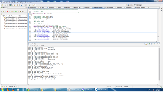
        I did the platform test for TMS320C6678 EVM. But I am not observing the NAND, NOR, EEPROM tests running. only LED test ,

    internal and external tests are running which are passed. 

    this is what I observed in Console.

    ***************************************************

    [C66xx_0] p_info->version = 2.00.00.14
    [C66xx_0] p_info->cpu.core_count = 8
    [C66xx_0] p_info->cpu.name = TMS320C6678
    [C66xx_0] p_info->cpu.id = 21
    [C66xx_0] p_info->cpu.revision_id = 0
    [C66xx_0] p_info->cpu.silicon_revision_major = 0
    [C66xx_0] p_info->cpu.silicon_revision_minor = 0
    [C66xx_0] p_info->cpu.megamodule_revision_major = 8
    [C66xx_0] p_info->cpu.megamodule_revision_minor = 1
    [C66xx_0] p_info->cpu.endian = 1
    [C66xx_0] p_info->board_name = TMDXEVM6678L
    [C66xx_0] p_info->frequency = 1000
    [C66xx_0] p_info->board_rev = 14
    [C66xx_0] p_info->led[PLATFORM_USER_LED_CLASS].count = 4
    [C66xx_0] p_info->led[PLATFORM_SYSTEM_LED_CLASS].count = 0
    [C66xx_0] p_info->emac.port_count = 2
    [C66xx_0] EMAC port 1 connected to the PHY.
    [C66xx_0] MAC Address = 40:5f:c2:b7:c2:b1
    [C66xx_0] Current core id is 0
    [C66xx_0] User switch 1 state is ON
    [C66xx_0] LED test start
    [C66xx_0] LED 0 ON
    [C66xx_0] LED 0 OFF
    [C66xx_0] LED 0 ON
    [C66xx_0] LED 1 ON
    [C66xx_0] LED 1 OFF
    [C66xx_0] LED 1 ON
    [C66xx_0] LED 2 ON
    [C66xx_0] LED 2 OFF
    [C66xx_0] LED 2 ON
    [C66xx_0] LED 3 ON
    [C66xx_0] LED 3 OFF
    [C66xx_0] LED 3 ON
    [C66xx_0] LED test complete
    [C66xx_0] Internal memory test start
    [C66xx_0] Internal memory test (for core 2) passed
    [C66xx_0] Internal memory test complete
    [C66xx_0] External memory test start
    [C66xx_0] External memory test passed
    [C66xx_0] External memory test complete
    [C66xx_0] Test completed

    *************************************************************

     I tried to debug the code to understand why cpu unable to run the NAND, NOR, EEPROM tests but I could not.

    So please let me know If any problem with board.

    thank you sir.

    regards,

    chandu.

  • Please take a look at "README.txt" file in the platform_test folder:

    C:\ti\pdk_C6678_x_x_x\packages\ti\platform\evmc6678l\platform_test

    There is a test configuration file pdk_#_##_##_##\\packages\ti\platform\evmc6678l\platform_test\testconfig with name platform_test_input.txt. Edit this file to change the configuration options. (Step 7 in README file above)

    By default those tests are disabled. You can set them to 1 to enable the testing.

    test_eeprom = 1
    test_nand = 1
    test_nor = 1

  • Hello,

    Thank you  for valuable information.

    Yes sir, I did the platform test as you suggested. now my board passed all the tests eeprom, NAND, NOR, LED, memory test. 

    So please inform me what would be the reason for why I am unable observe the clock at SPI_clock and data at SPI_MOSI pins.

    ************************************

    [C66xx_0] p_info->version = 2.00.00.14
    [C66xx_0] p_info->cpu.core_count = 8
    [C66xx_0] p_info->cpu.name = TMS320C6678
    [C66xx_0] p_info->cpu.id = 21
    [C66xx_0] p_info->cpu.revision_id = 0
    [C66xx_0] p_info->cpu.silicon_revision_major = 0
    [C66xx_0] p_info->cpu.silicon_revision_minor = 0
    [C66xx_0] p_info->cpu.megamodule_revision_major = 8
    [C66xx_0] p_info->cpu.megamodule_revision_minor = 1
    [C66xx_0] p_info->cpu.endian = 1
    [C66xx_0] p_info->board_name = TMDXEVM6678L
    [C66xx_0] p_info->frequency = 1000
    [C66xx_0] p_info->board_rev = 14
    [C66xx_0] p_info->led[PLATFORM_USER_LED_CLASS].count = 4
    [C66xx_0] p_info->led[PLATFORM_SYSTEM_LED_CLASS].count = 0
    [C66xx_0] p_info->emac.port_count = 2
    [C66xx_0] EMAC port 1 connected to the PHY.
    [C66xx_0] MAC Address = 40:5f:c2:b7:c2:b1
    [C66xx_0]
    [C66xx_0] NAND Device:
    [C66xx_0] p_device->device_id = 54
    [C66xx_0] p_device->manufacturer_id = 32
    [C66xx_0] p_device->width = 8
    [C66xx_0] p_device->block_count = 4096
    [C66xx_0] p_device->page_count = 32
    [C66xx_0] p_device->page_size = 512
    [C66xx_0] p_device->spare_size = 16
    [C66xx_0] p_device->column = 512
    [C66xx_0] p_device->handle = 8246
    [C66xx_0] p_device->flags = 0
    [C66xx_0] p_device->bboffset = 5
    [C66xx_0] Bad Block Table (only bad block numbers shown):
    [C66xx_0]
    [C66xx_0] NOR Device:
    [C66xx_0] p_device->device_id = 47896
    [C66xx_0] p_device->manufacturer_id = 32
    [C66xx_0] p_device->width = 8
    [C66xx_0] p_device->block_count = 256
    [C66xx_0] p_device->page_count = 256
    [C66xx_0] p_device->page_size = 256
    [C66xx_0] p_device->spare_size = 0
    [C66xx_0] p_device->handle = 47896
    [C66xx_0] p_device->flags = 0
    [C66xx_0] p_device->bboffset = 0
    [C66xx_0]
    [C66xx_0] EEPROM Device (@ 0x50):
    [C66xx_0] p_device->device_id = 80
    [C66xx_0] p_device->manufacturer_id = 1
    [C66xx_0] p_device->width = 8
    [C66xx_0] p_device->block_count = 1
    [C66xx_0] p_device->page_count = 1
    [C66xx_0] p_device->page_size = 65536
    [C66xx_0] p_device->spare_size = 0
    [C66xx_0] p_device->handle = 80
    [C66xx_0] p_device->flags = 0
    [C66xx_0] p_device->bboffset = 0
    [C66xx_0]
    [C66xx_0] EEPROM Device (@ 0x51):
    [C66xx_0] p_device->device_id = 81
    [C66xx_0] p_device->manufacturer_id = 1
    [C66xx_0] p_device->width = 8
    [C66xx_0] p_device->block_count = 1
    [C66xx_0] p_device->page_count = 1
    [C66xx_0] p_device->page_size = 65536
    [C66xx_0] p_device->spare_size = 0
    [C66xx_0] p_device->handle = 81
    [C66xx_0] p_device->flags = 0
    [C66xx_0] p_device->bboffset = 0
    [C66xx_0] Current core id is 0
    [C66xx_0] User switch 1 state is ON
    [C66xx_0] EEPROM test start
    [C66xx_0] test_eeprom: passed
    [C66xx_0] EEPROM test complete
    [C66xx_0] NAND test start
    [C66xx_0] test_nand: passed
    [C66xx_0] NAND test complete
    [C66xx_0] NOR test start
    [C66xx_0] test_nor: passed
    [C66xx_0] NOR test complete
    [C66xx_0] LED test start
    [C66xx_0] LED 0 ON
    [C66xx_0] LED 0 OFF
    [C66xx_0] LED 0 ON
    [C66xx_0] LED 1 ON
    [C66xx_0] LED 1 OFF
    [C66xx_0] LED 1 ON
    [C66xx_0] LED 2 ON
    [C66xx_0] LED 2 OFF
    [C66xx_0] LED 2 ON
    [C66xx_0] LED 3 ON
    [C66xx_0] LED 3 OFF
    [C66xx_0] LED 3 ON
    [C66xx_0] LED test complete
    [C66xx_0] Internal memory test start
    [C66xx_0] Internal memory test (for core 2) passed
    [C66xx_0] Internal memory test complete
    [C66xx_0] External memory test start
    [C66xx_0] External memory test passed
    [C66xx_0] External memory test complete
    [C66xx_0] Test completed

    *************************************************************

    and my source code for SPI is mentioned in previous posts. So please help me sir.

    thank you sir.

    regards,

    chandu.

  • Hi sir,

    I have doubt regarding TMDSEVM6678 spi programming.

    That is, what boot configuration should I need to maintain to run my own Source code for SPI.

    thank you sir.

    regards,

    chandu.