


Hi,
We would like to ask about the mechanism of USB OTG device recognition:
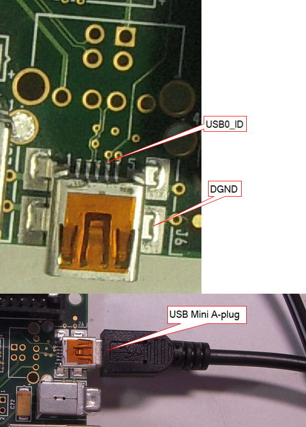
The attached picture is taken from an evaluation board of TI’s OMAPL138 processor, and the header shown is a USB Mini-AB receiver. The 2nd pin from the right in the upper sub-image is connected to processor’s USB0_ID pin. According to USB standard:
(1) A peripheral would draw this USB0_ID to GND, and this would notify the evaluation board’s USB controller to assume the role of host and hence drive VBUS.
(2) A host would drive USB0_ID high, notifying the evaluation board’s USB controller to act as peripheral.
We do not currently have a USB Mini-B header (and do not have OTG host device). We guess that:
For peripheral device to achieve (1) above, the peripheral device needs to tie USB0_ID and DGND together.
What we actually found is that this USB0_ID↔DGND is done by the Mini-A plug.
1. When Mini-A plug is NOT plugged into the Mini-AB receiver, the resistance between USB0_ID and DGND is 192kΩ.
2.After Mini-A plug is plugged, the resistance between USB0_ID and DGND is 192kΩ becomes 0.
From this we know that USB0_ID and DGND pins must be tied internally within the Mini-A plug.
For external host to achieve (2) above, it seems that the corresponding Mini-B plug must NOT tie USB0_ID and DGND. Instead, it will tie USB0_ID to VBUS which the connected external host is driving.
Is this guess correct? We need to confirm this before making the board because we have no B device/plug to make the test.
Additionally, could someone refer me to the official USB documentation describing the electrical connection within A and B OTG plugs? I have read several documents in USG.org but didn’t find one giving such information.
Paul
