This thread has been locked.

If you have a related question, please click the "Ask a related question" button in the top right corner. The newly created question will be automatically linked to this question.

AM335x RGMII Interface specification

Other Parts Discussed in Thread: DP83865

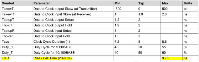
For the RGMII Interface, there are two modes, i.e. the HP mode and the 3COM mode.
The difference between the HP mode and the 3COM mode seems to be the timing characteristics.

Which mode of the HP and the 3COM does AM335x support? Is it only the 3COM mode?

Best regards,

Daisuke


  • Information: DP83865 PHY supports the HP mode and the 3COM mode.

    Best regards,

    Daisuke


  • If the PCB was designed with the transmit and receive clocks having the same propagation delay as their respective data paths, the DP83865 RGMII PHY would need to be configured to operate in 3COM mode when connected to AM335x.

    If the PCB was designed to provide the additional 1.8ns +/- 300ps propagation delay on the transmit and receive clock signals relative to their respective data paths, the DP83865 RGMII PHY would need to be configured to operate in HP mode when connected to AM335x.

    Regards,
    Paul

  • Hi Paul,

    Thank you for your reply.

    Best regards,

    Daisuke


  • Hi Paul-san,
    Please tell me the signal transition levels for RGMII timing parameters.
    I have already got the information for all input and output timing parameters.
    All input and output timing parameters are referenced to 50% I/O voltage for both "0" and "1" logic levels.
    All rise and fall transition timing parameters referenced to VIL MAX and VIH MIN for input clocks, VOL MAX and VOH MIN for output clocks.
    Can this be applied for RGMII?
    I am concerned about the transition levels for RGMII because the RGMII v2.0 specifications describe that Rise / Fall Time is 20-80%.
    Table 1. RGMII v2.0 Timing Requirements
    Best regards,
    Daisuke
  • Hi Paul-san,
    Please give me an answer as soon as possible. Your prompt reply would be appreciated.
    Best regards,
    Daisuke
  • As you pointed out, the maximum rise/fall time defined by the RGMII specification is 0.75ns when measured from 20% to 80% of the signal swing.

    The output rise/fall times should be within the RGMII specification when connected to a typical RGMII PHY.

    What is your specific concern?

    Regards,
    Paul

  • Hi Paul-san,

    Thank you for your reply.

    I am concerned about the IO voltage being different between RGMII standard and AM335x RGMII. RGMII v1.3 uses 2.5V and RGMII v2.0 uses 1.5V, but AM335x RGMII uses 1.8V or 3.3V.

    Best regards,

    Daisuke
  • Most RGMII PHYs support standard 1.8 volt or 3.3 volt CMOS logic levels. What PHY do you plan to use? Have you checked if it will support these logic levels?

    Regards,
    Paul  

  • Hi Paul-san,

    Thank you for your reply.

    Our customer is using DP83867 as PHY.

    DP83867 supports 1.8v or 3.3v CMOS logic level and it defines that the maximum rise/fall time is 0.75ns when measured from 20% to 80% of the signal swing.

    AM335x supports 1.8v or 3.3v CMOS logic level and it defines that the maximum rise/fall time is 0.75ns but it does not define when it was measured.

    For AM335x RGMII specifications, was the maximum rise/fall time measured from 20% to 80% of the signal swing?

    Best regards,

    Daisuke
  • Hi Paul-san,

    Daisuke Maeda said:

    AM335x supports 1.8v or 3.3v CMOS logic level and it defines that the maximum rise/fall time is 0.75ns but it does not define when it was measured.

    For AM335x RGMII specifications, was the maximum rise/fall time measured from 20% to 80% of the signal swing?


    Please give me an answer as soon as possible. Your prompt reply would be appreciated. Sorry for taking your precious time.

    Best regards,

    Daisuke