This thread has been locked.

If you have a related question, please click the "Ask a related question" button in the top right corner. The newly created question will be automatically linked to this question.

[C6748] query about DVDD18 pull up to 2.7V

Other Parts Discussed in Thread: TPS65023

My customer reported that DVDD18 went up to 2.7V after replacing C6748 from ZWT package to ZCE package. When ZWT package was used, this issue was not found. tps65023 is used for pmic. (VLDO1->DVDD18, DCDC2->DVDD3318)  

The issue is desribed in Silicon Errata, but the customer wants to make clear whether this issue is related to package type. If not, which factor from C6748 perspective would affect this issue?


  • Hi Lloyd Hwang,

    This is not related to package. As described in the silicon errata this is based on 1.8V load current.

    Please refer the work around for this issue explained in the silicon errata to fix it.

    May be due to slight process variation in Silicon, temperature and voltage the customer may not see this issue in ZWT package.

    Regards

    Antony

    • --------------------------------------------------------------------------------------------------------
      Please click the Verify Answer button on this post if it answers your question.
      --------------------------------------------------------------------------------------------------------
  • Hi Antony,

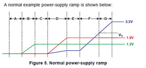
    Our customer tries the workaround 1-(b) for this issue. They demand that the shunt regulator controls the voltage at DVDD18 only between 1.8V and 1.8V+Vt.

    What's the voltage of the Vt?

    Best regards,

    Daisuke


  • Hi,

    Please give me an answer as soon as possible.
    Your prompt reply would be appreciated.

    Best regards,

    Daisuke


  • Hi Antony,

    Can the voltage range of Vt not be defined?

    Best regards,

    Daisuke


  • Daisuke,

    Apologies for the delay in response, I have already forward your request to internal colleague and there is a delay in response due to thanks giving vacation will get back to you soon.

    Regards

    Antony 

  • Maeda-san,

    Vt for the IO transistors is in the range of 0.5V to 0.6V.

    Rgds,

    Sunil

  • Hi Sunil and Antony,

    Thank you for your reply and your cooperation.

    Best regards,

    Daisuke


  • Hi Sunil,

    Our customer has a problem for the workaround 1-(a). When using 300uF bulk capacitance, it is effective on their most boards, but it is not effective on the some boards. When using 600uF bulk capacitance, it is effective on their all boards. 300uF bulk capacitance is sufficient for their boards because the ramp time of 3.3V supply on their boards is shorter than 1 ms. So they doubt the characteristic related to this problem is uniform in all devices.

    Can you guess why the high bulk capacitance is required on their board?

    Best regards,

    Daisuke


  • Hi Daisuke-san

    The 140 mA number in the errata is max across process, voltage and temperature.

    The errata states the following

    Maintain sufficient bulk capacitance on the DVDD18 supply such that the charging current for these capacitors provides all or part of the required >140 mA. Bulk capacitance in this context means the total capacitance seen by the DVDD18 supply (filter capacitors, bypass capacitors, etc.). Capacitor charging current is defined as I = C*(dV/dt). So the ramp rate of the DVDD3318_x supply and the total bulk capacitance on the DVDD18 supply can be used to calculate the current produced.

    So the questions to ask will be

    1) How many boards tested, how many work vs how many fail?

    2) How is the 300-600 uF bulk capacitance being implemented?

    3) Are they absolutely sure that the slew rate/ramp time is less than 1 msec across all the boards?

    4) All boards made at the same time, same manufacturer etc or different builds?

    5) Can they share their power supply snapshots for working and failing cases?

    Regards

    Mukul

  • Hi Mukul,

    Thank you for your reply. Sorry for my late reply.

    Mukul Bhatnagar said:

    1) How many boards tested, how many work vs how many fail?

    120 boards were tested, and 115 boards worked, and five boards failed.

    Mukul Bhatnagar said:

    2) How is the 300-600 uF bulk capacitance being implemented?

    Please see the attached schematic.

    6837.電源回路_140219.pdf

    The power supplies which are supplied to the C6746 as follows:

     1V2D_DSP(1.2V) 1V8D_DSP(1.8V)  3V3D_DSP(3.3V)

    There are three bulk capacitors on the 1.8V line, but one of capacitors cannot be seen in this schematic because the DSP side has it.

    Mukul Bhatnagar said:

    3) Are they absolutely sure that the slew rate/ramp time is less than 1 msec across all the boards?

    No. They only checked it on some boards made early. The timing diagram is attached.

    2234.PT#1電源onタイミング_131012.pdf

    Mukul Bhatnagar said:

    4) All boards made at the same time, same manufacturer etc or different builds?

    All boards were not made at the same time.

    Mukul Bhatnagar said:

    5) Can they share their power supply snapshots for working and failing cases?

    Yes. But they cannot check them soon.

    Best regards,

    Daisuke


  • Hi Daisuke,

    They are using LDO regulator to power the 1.8V rail that is having minimum output current of 200mA 300mA (Typical Limit) no maximum limit.

    Torex semiconductor: XC6415AA28

    1.8V Loads

    1. Shunt resistor 330 ohm and 330uF Bulk capacitor at the LDO output -5.45mA
    2. C6748 -  for 1.8V rail (IDDQ) – 180mA
    3. DDR memory 100 mA at worst condition
    4. Taking Inrush current into consideration

    By considering all the facts the 300mA output current of the LDO regulator does no the meet the actual load requirement and the load on the DVDD18 supply during the DVDD13318_x supply ramp does not exceeds 140 mA with the 300uF bulk capacitor in some boards.

    Note: We don’t know how much the board exactly sinks current from the 1.8V rail.

    By adding larger value of extra bulk capacitor 600uF supplies even more of the current demand locally, requiring less from the LDO output and act as a local current source.

    We basically suggest using the high-efficiency switching regulators with the peak current of 500mA in our power application notes. They can check the failing board with the external power supply with 300uF buck capacitor to see it gets pass for sanity check.

    Regards

    Antony

  • Hi Antony,

    Thank you for your reply.

    DDR memory is not implemented on the customer boards. Therefor the output current of the LDO regulator should meet the actual load requirement.

    Antony Samsunil said:

    1.8V Loads

    1. Shunt resistor 330 ohm and 330uF Bulk capacitor at the LDO output -5.45mA
    2. C6748 -  for 1.8V rail (IDDQ) – 180mA
    3. DDR memory 100 mA at worst condition
    4. Taking Inrush current into consideration

    How was the current consumption for C6748 estimated?

    Best regards,

    Daisuke


  • Hi Daisuke,

    I have the extracted the power consumption from the Power app note for C6748


    PIN NAME

    VOLTAGE (1)  (2)

    (V)

    Imax

    (mA)

    TOLERANCE

    SEQUENCING ORDER

    TIMING DELAY

    I/O

    RTC_CVDD

    1.2

    1

    –25%, +10%

    1 (3)


    Core

    CVDD (4)

    1.0 / 1.1 / 1.2

    600

    –9.75%, +10%

    2


    I/O

    RVDD, PLL0_VDDA, PLL1_VDDA, SATA_VDD, USB_CVDD, USB0_VDDA12

    1.2

    200

    –5%, +10%

    3


    I/O

    USB0_VDDA18, USB1_VDDA18, DDR_DVDD18, SATA_VDDR, DVDD18

    1.8

    180

    ±5%

    4


    I/O

    USB0_VDDA33, USB1_VDDA33

    3.3

    24

    ±5%

    5


    I/O

    DVDD3318_A, DVDD3318_B, DVDD3318_C

    1.8 / 3.3

    50 / 90 (5)

    ±5%

    4 / 5


    But we don’t exactly how much the customer board sinks current from the 1.8V LDO supply, Can you try check the failing board with external power supply.

    How they implemented power plane for 1.8V supply separate plane or split plane in the PCB? Or high width trace greater than 20Mils.

    Regards

    Antony

  • Hi Antony,

    Thank you for your reply. Sorry for my late reply.

    There is no update from the customer. If there is a update, I will come back here.

    Best regards,

    Daisuke