


Hi,
There seems to a potential pitfall in following LogicPD’s EXPL138 design:
In the design net USB_VBUS (actually only USB0’s VBUS) is connected simultaneously with
(1) L138’s USB0_VBUS pin (N19, on the SOM)
(2) USB charger input of PMIC TPS65070 (pin 12, on the SOM)
(3) USB OTG connector J6 (on the baseboard)
as shown in the compiled schematic below (combined parts from baseboard and SOM schematic).
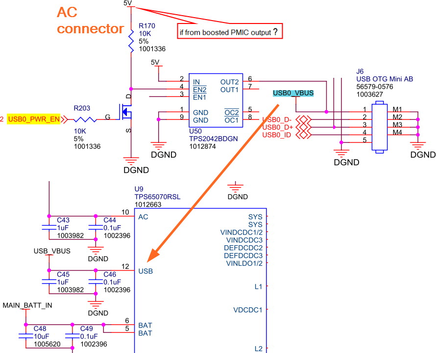
If there is a slave device connecting to the Mini-AB connector J6, it will pull USB0_ID to GND, and consequently cause L138’s USB0 controller to assume the rule of host, which will then drive USB0_PWR_EN (which is actually from USB0_DRVVBUS, pin K18) (see left in the picture) high, which then turns on OUT2 at switch U50, and USB0_VBUS will be powered by the 5V DC power.
But there is a potential danger of SELF-CURRENT-LOOP:
If the 5V input to U50 is actually derived from PMIC, for example, boosted from a 3.3V output of PMIC, then would we be charging PMIC/battery with its own output? The current loop would be like:
Battery → PMIC → 3.3V → boosted to 5V → USB0_VBUS → PMIC → battery
Although EXPOMAPL138 connects U50 switch only to 5V AC input, if we want to use the USB host functionality on battery we would need to implement the said “boost”, and in that situation the scenario above becomes a reality.
In that case, how could we do to prevent the SELF-CHARGING-LOOP? Upon deciding USB0 controller’s role as the host so that it needs to use USB0_DRVVBUS to turn on the switch for delivering power on VBUS to the peripheral, should we
- Use I2C to turn TPS65070’s USB power OFF (register 01h, bit 5) ?
- or use a simple switch controlled by USB0_DRVVBUS, for example a transistor, to cut off the connection between VBUS net and PMIC’s USB input?
Paul
