This thread has been locked.

If you have a related question, please click the "Ask a related question" button in the top right corner. The newly created question will be automatically linked to this question.

GPMC waveform missing the second half-word

Other Parts Discussed in Thread: AM3894

We are witnessing instabilities while using the Sitara AM3894. For the sake of clarity, I will mention the "good_board" and a "bad_board".
The major difference between those 2 boards is the length of the traces between the GPMC and the FPGA (~80mm but poorly matched on the good_board and 100mm on the  bad one)

I will bound my description on one failure mode, at 62MHz of this interface. We have different setups with other failure modes, but this one is the easiest to communicate.

The technical description is as follow:
The problem is around the GPMC. Our GPMC settings are the following for the ChipSelect0 device:
GPMC_CONFIG1 = 0x28601011   # general config
GPMC_CONFIG2 = 0x00020300   #  CS# timings
GPMC_CONFIG3 = 0x00010200   #  ALE timings
GPMC_CONFIG4 = 0x01000201   #  WE# and OE#
GPMC_CONFIG5 = 0x00020304   #  cycle time
GPMC_CONFIG6 = 0x00000000   #  intercycles time

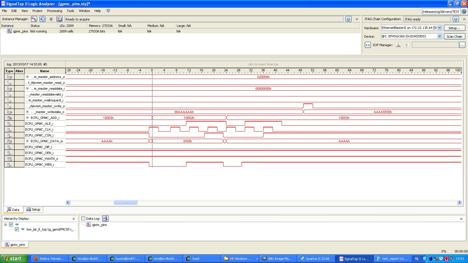
The test consists in writing a check pattern (0xaaaa5555) through the GPMC to our external FPGA.

On the good_board if have the attached "good_wf.jpg" access waveform for the write accesses.
On the the bad_board, I have the attached "bad_wf.jpg" access waveform for the write accesses, which as you see is missing the second halfword...
These waveforms are captured using a free running 375MHz clock on the FPGA side, much like a "Timing acquisition" logic analyzer would do it.

So the problem seems to be a failure of the control mechanism of the GPMC.
From the initial analysis I have made, the only reasonable source of discrepancy is a timing mismatch on the WAITN pin. But as you can see on the waveforms WAITN is stuck at one, and furthermore how can it propagate as a control error in the GPMC ?

I think I will need help to clarify that, and to quantify the timing budget on this interface.

The TI references are:
Our device_ID in both case is
0x48140600: 0x1B81E02F (silicon rev1.1)

  • We would really need help from the support team on this one, since we have no way of understanding the failure mode in the GPMC...

    Is anyone looking at it ?

  • Hi Nicolas,

    - Regarding the "good_board" and "bad_board" how does the signal integrity look like?
    Do you have some oscilloscope screenshot that show how the Ctrl signal look like?
    Have you done some IBIS simulation on the GPMC signal on both the "good_board" and "bad_board"?

    I think that before we try to analyze the failure mecanism we need to be sure that the signal meet the specification.

    - You seem to be using rev 1.x silicon while the latest silicon is rev 2.1.
    Moving forward only AM3892C (ie rev 2.1) will be orderable so I would advise to test on the latest silicon revision for the final testing before going to prodction.
    Also what is the CPU clk frequency used? AM3892C is qualified at 1.35GHz.

    Anthony

  • Thanks for you questions:

    • We don't have signal integrity figures for the signals
    • We didn't do IBIS simulations
    • I am refining my timing constraints

    BUT, because we are talking about write accesses(nb. for reads the data line would be concerned also), the only ctrl signal that can affect the GPMC is the WAITN pin. and if you look at the waveform the WAITN doesn't toggle.

    Granted, those are not oscilloscope waveform, but we are alone on the GPMC bus, so the WAITN line is a straight copper trace.

    All GPMC lines are length aligned, and 50 single ended matched.

    The CPU clock frequency is the default one: 1GHz (987.42 to be exact)

  • Nicolas,

    I have made some comments on your other post regarding the max GPMC_CLK speed supported.

    Anthony