This thread has been locked.

If you have a related question, please click the "Ask a related question" button in the top right corner. The newly created question will be automatically linked to this question.

uPP software reset issue

Other Parts Discussed in Thread: TMS320C6657, OMAP-L138, AM1806

Hi,

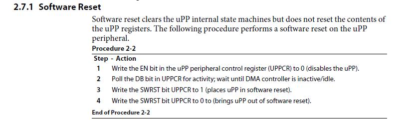
My customer has trying uPP software reset C6655 device.

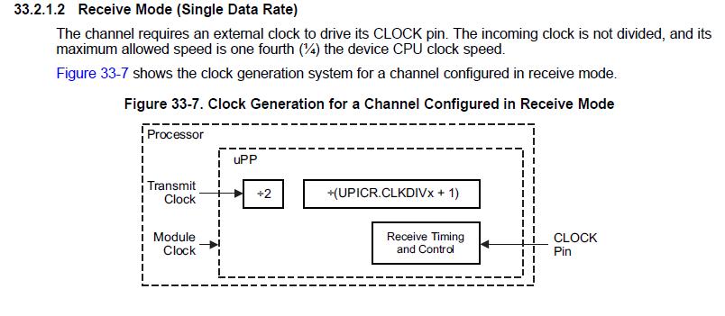
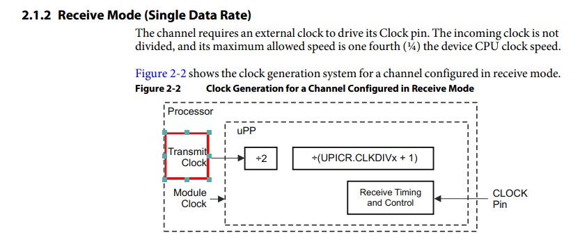
uPP is used in receive mode and connected to the FPGA.

During normal operation, uPP is receiving data from the FPGA successfully. but, after running the uPP software reset, Sometime It is not able to receive data from FPGA. It seems that uPP internal DMA is not driven, even though FPGA data transfer to uPP.

Do you have any idea to solve the problem?

Best regards,

Chi

  • Chi,

    For the software reset:
    The first step is to write EN=0 in UPPCR. So the software reset should send WAIT signal.
    Please have a look at section "Emulation Considerations" in UPP user guide.
    It says that uPP module (in receive mode) will assert WAIT signal if the stop-running conditions are met,
    which includes EN bit =0 in the uPP peripheral control register (UPPCR).

  • Hi, Pubesh

    Thank you for your reply.

     Customer is running a software reset process that is described in the uPP UG(SPRUHG9). So set to UPPCR.EN = 0 at first.


    My customer update the following infomaiton.

    uPP can be received data normally after software reset, when  FPGA is supplied to DSP uPP_CLK also run-time software reset sequence. (It was stopped uPP_CLK software reset processing period then it can not receive data.)


    So, I have question.

    1. Why would it can receive data when FPGA supplied clock to DSP during software reset processing ?

    2. UPP_CLK Should be supplied during software reset processing ?


    Best regards,

    Chi

  • CLOCK - Driven by transmitter.
    In transmit mode, CLOCK is an output signal.
    In receive mode, CLOCK is an input signal.
    Software reset clears the uPP internal state machines but does not reset the contents of the uPP registers.
     
    UPP receive channel:
    The uPP peripheral will not drive ENABLE in receive mode, so the line should always reflect the value being driven by the FPGA.

  • I had known that CLOCK is input signal in receive mode. So, FPGA drive the CLOCK signal when uPP is receive mode.

    The customer made following experiment.

     - uPP is receive mode.

    1. Data transfer completion from FPGA to DSP.    (FPGA does not drive uPP Clock when the data transfer is finished.)

    2. FPGA drive the uPP clock supply only.

    3. DSP perform the uPP Software reset processing.

    4. uPP register re-initialization    (2.6.1 Step-by-Step Procedure: run the step 5 or later)

    5. FPGA stop the uPP clock supply.

    6. Next data transfer from FPGA to DSP.

    It is OK if uPP clock is supplied from FPGA to the Softare reset process as described above. but, uPP can not receive the next data when uPP clock does not supply from the FPGA during the software reset. It seems that uPP DMA is not working.

    Shoud we countinue to supply uPP clock during software reset if uPP is in receive mode?


    Best regards,

    Chi

  • Chi,

    Please kindly verify the UPP Clock register (0x0262016C) and refer the datasheet(tms320c6657.pdf)

  • Hi, Pubesh

    My custmor set to UPP_TX_CLKSRC = 0 and FPGA supply 70Mhz uPP clock to DSP, but Is there related to this register setting in uPP receive mode?

    So, I want to know following point.

    Q1: should FPGA supply uPP clock during software reset in receive mode?(Handling uPP clock during Software Reset is not described in the document)


    Q2: Is it should continue to supply How much uPP clock?     (Need until Software Reset sequence(2.7.1 Software Reset(SPRUHG9)) finished?)


    Best regards,

    Chi

  • Hi Pubesh,

    I'd like to modify the questions for clarification.


    Q1: Should FPGA supply uPP clock during software reset in receive mode?

    Q2: What timing the clock should be supplied for the software reset ?

                - after previus uPP data received from FPGA to DSP.

               e.g 1.  clock start: before disable the uPP (UPPCR.EN = 0)

                          clock stop: after Software Reset sequence finished

           <note>  Software Reset sequence  Refer to 2.7.1 Software Reset on SPRUHG9

               e.g 2. We should not stop the uPP_CLOCK any time.


    Your cooperation is greatly appreciated.

    Best regards,

    Chi

  • Chi-san,
    I have requested for help with team,We will get back to you on the same.

  • Have you tried probing the WAIT signal after software reset in both cases (clock supplied and not supplied)? What are your observations?

  • Hi, Aditya

    I am grateful to your help.

    My customer checking the WAIT signal after software reset, WAIT signal was negated.

    In fact, WAIT signal is driven High. Because the customer is changing the polarity of the WAIT signal(UPICR.WAITPOLB = 1)).

    WAIT signal status was the same in both cases (clock supplied and not supplied).

    WAIT signal is always driven as negate in receive mode, isn't it ?


    Best regards,

    Chi

  • Hi, Aditya


    My customer is in a very great hurry! They had to fix the FPGA control to DSP by last month.

    I would be grateful if you could reply as soon as possible. Please ask me anything if you need more information.


    Best regards,

    Chi

  • Hi,

    Sorry for the delay in getting back. We were on Thanksgiving break during the latter part of last week.

    I have requested the team for support. Will get back shortly.

  • Hi,

    In general, any MMR based reset to work, the module needs to have a clock.

    So why you expect the SWRESET to work w/o the clocks being supplied?

    Thanks.

  • Hi, Rajasekaran K


    Thank you for your reply.

    I understood that uPP software reset must be supplied external clock in receive mode.


    > So why you expect the SWRESET to work w/o the clocks being supplied?

    I was thinking that software reset is uPP module's intanal state control, So I did not think external clock signal to affect.

    Because uPP initialization sequence after device reset out is running a software reset without the clocks being supplied, or uPP does not output clocks.

     <note>  Step 3 of Software Reset sequence  Refer to 2.7.1 Software Reset on SPRUHG9


    Best regards,

    Chi

  • Hi, Rajasekaran K


    Do I need to supply the clock also uPP initialization?


    Best regards,

    Chi

  • Hi, peaves


    I'm sure that you have a million things on your plate.

    It's very important that we receive your reply.


    I await your reply.


    Best regards,

    Chi

  • Chi-San,

    My apologies for the same. If the issue is on uPP implementation and associated FPGA interface,
    The MityDSP board that has the FPGA with OMAP-L138 (uPP) implementation for your reference only.

    MityDSP-L138F:
    http://www.mitydsp.com/mitydsp-l138f
    http://www.mitydsp.com/upp

    Please have a look at the below link for uPP Design Considerations,
    http://support.criticallink.com/redmine/projects/arm9-platforms/wiki/UPP_Design_Considerations
    Software Reset test code is avilable at the below link for reference, see the DspUpp[1].cpp file.
    http://support.criticallink.com/redmine/projects/arm9-platforms/wiki/Sample_uPP_Device_Driver

    Please double check your code for software reset, Maybe some issue occure when you are doing improper reset of the UPP peripheral.
    Refer the below thread and wiki articles, this will help you.
    http://e2e.ti.com/support/dsp/omap_applications_processors/f/42/p/96625/440526.aspx#440526
    http://processors.wiki.ti.com/index.php/Introduction_to_uPP#High-Speed_Data_Transfer_to_FPGA_or_External_uPP
    http://processors.wiki.ti.com/index.php/Using_the_uPP_DSP/BIOS_Driver#Run-Time_Initialization
    If possible please provide a code snippet so that we can examine this issue.

  • Hi, Pubesh-san


    Thank you for your reply and suggestion.


    See attached the customer's uPP software reset sequence.

    I has confirmed DspUPP.cpp, but I think so that there is not much difference to the procedure of customer.


    Please let us know if there's anything which catches your attention.

    and, Please tell me my understanding that uPP software reset must be supplied external clock in receive mode is correct.


    Best Regards,

    Chi

  • Sorry, Please check the attached file.


    Best Regards,

    Chi

  • Chi-San,

    You are trying to initializing the uPP peripheral and not resetting from your code snippet.
    Please refer the below sections at the UPP user guide(spruhg9).
    2.6.1  Section for uPP initializing
    2.7.1 Section for uPP resetting

    We can use the below code until unless hardware want to uPP get initialized.

    void uppdrv_internal_reset()
    {
     UPPREGS.UPPCR.BIT.EN = 0; //disable uPP
     
     while(UPPREGS.UPPCR.BIT.DB == 1); //wait until DMA controller is inactive/idle.

     //uPP reset begins
     UPPREGS.UPPCR.BIT.SWRST = 1; //places uPP in software reset

     for(ii=0;ii<200;ii++);// wait 200 clock cycles

     UPPREGS.UPPCR.BIT.SWRST = 0;  //brings uPP out of software reset
     UPPREGS.UPPCR.BIT.EN = 1; //brings out of from disable mode (enable uPP)
    }

    Here, Software reset clears the uPP internal state machines but does not reset the contents of the uPP registers.
    If the uPP peripheral is coming out of from POR, then can initialize the uPP(Refer the section 2.6.1).
    Otherwise better to use software reset code alone(Refer the section 2.7.1).

    Chi said:
    Please tell me my understanding that uPP software reset must be supplied external clock in receive mode is correct.


    Yes, you are correct.

  • Chi-San,

    Maybe missed to set MODE bit to 3h in UPPCR register.
    When you are trying to initialize the uPP as per the following configuration,
    1.Single data rate
    2.Duplex mode (MODE bit is necessary for dual channel access)
    3.16 bit interface
    4.Digital loop back mode

    void uppdrv_internal_reset()
    {
            s32 ii;
            UN_UPICR_REG upicr_reg;
    
    //reset begins
            UPPREGS.UPPCR.BIT.EN = 0; 
            while(UPPREGS.UPPCR.BIT.DB == 1);
    
            UPPREGS.UPPCR.BIT.SWRST = 1; 
            for(ii=0;ii<200;ii++);
            UPPREGS.UPPCR.BIT.SWRST = 0; 
    
            UPPREGS.UPPCR.BIT.FREE = 1;	//Free run is enabled.
            UPPREGS.UPPCR.BIT.SOFT = 0;	//Soft stop is disabled.
            UPPREGS.UPPCR.BIT.RTEMU = 0;	//Real-time emulation enabled. Peripheral halts transactions while program is halted.
    
            UPPREGS.UPDLB.BIT.AB = 1;	//Enable A-to-B digital loopback. Requires BA = 0 and the MODE bit in the uPP channel control register
    (UPCTL) to be set to 3h.
    
    //TODO: Duplex Mode 1. Channel A transmits and Channel B receives. Requires CHN = 1.
    
    
    //TODO: MODE bit to be set to 3H
    
    
            UPPREGS.UPDLB.BIT.BA = 0;	//see above line
            UPPREGS.UPCTL.BIT.DDRDEMUX = 0;  //Disable the Double data rate demultiplexing mode. 
    
            UPPREGS.UPCTL.BIT.CHN = 1;	Dual channel mode
    
    
            uppdrv_duplex_mode(UPPM_DUPLEX1); 
    
    /* For Channel A */
            UPPREGS.UPCTL.BIT.DRA = 0;	//Single data rate
    
            UPPREGS.UPCTL.BIT.IWA = 1;	//16-bit interface
    
            UPPREGS.UPCTL.BIT.DPWA = 0;	//No data packing (8-bit or 16-bit case)
    
            UPPREGS.UPCTL.BIT.DPFA = 0;	//Right-justified, zero extended
    
    
    /* NOTE!! 32bit access */
            upicr_reg._DWORD = UPPREGS.UPICR._DWORD;
            upicr_reg.BIT.STARTPOLB = 1;	//TODO: need to chk 
            upicr_reg.BIT.ENAPOLA = 0;
            upicr_reg.BIT.WAITPOLA = 0;
            upicr_reg.BIT.STARTA = 0;
            upicr_reg.BIT.ENAA = 1;
            upicr_reg.BIT.WAITA = 0;
            upicr_reg.BIT.CLKDIVA = 2;
            upicr_reg.BIT.CLKINVA = 0;
            upicr_reg.BIT.TRISB = 0;	//TODO: need to chk 
            UPPREGS.UPICR._DWORD = upicr_reg._DWORD;
            UPPREGS.UPIVR.BIT.VALA = (u32)0x0004; 
            UPPREGS.UPTCR.BIT.TXSIZEA = 0; 
    
            UPPREGS.UPIES.BIT.DPEI = 0;
            UPPREGS.UPIES.BIT.UORI = 0;
    /* B ch */
            UPPREGS.UPCTL.BIT.DRB = 0;	//Single data rate
    
            UPPREGS.UPCTL.BIT.IWB = 1;	//16-bit interface
    
            UPPREGS.UPCTL.BIT.DPWA = 0;	//TODO: again DPWA instead of DPWB
            UPPREGS.UPCTL.BIT.DPFB = 0;	//Right-justified, zero extended
    
    //      UPPREGS.UPCTL.BIT.SDRXIL = 0;	//Disable. Each peripheral channel is associated with its own DMA channel
    
    
    /* NOTE!! 32bit access */
            upicr_reg._DWORD = UPPREGS.UPICR._DWORD;
            upicr_reg.BIT.STARTPOLB = 0;
            upicr_reg.BIT.ENAPOLB = 0;
            upicr_reg.BIT.WAITPOLB = 0;
            upicr_reg.BIT.STARTB = 0;
            upicr_reg.BIT.ENAB = 1;
            upicr_reg.BIT.WAITB = 0;
            upicr_reg.BIT.CLKDIVB = 2;
            upicr_reg.BIT.CLKINVB = 0;
            upicr_reg.BIT.TRISB = 1;	//Channel B high-impedance state. Controls interface Channel B while idle in transmit mode. Only applies
    when Channel B is configured in transmit mode using the MODE bit in the uPP channel control register
    (UPCTL).
    
    //TODO: Need to set MODE bit
    
            UPPREGS.UPICR._DWORD = upicr_reg._DWORD;
    
            UPPREGS.UPIVR.BIT.VALB = (u32)0x0003;
            UPPREGS.UPTCR.BIT.TXSIZEB = 0;	//64 bytes threshold value to tx
            UPPREGS.UPTCR.BIT.RDSIZEI = 0;	//64 bytes threshold value to rx (DMA ch 1)
            UPPREGS.UPTCR.BIT.RDSIZEQ = 0;	//64 bytes threshold value to rx (DMA ch 2)
    
            UPPREGS.UPIES._DWORD = 0x00000000;
            UPPREGS.UPIER._DWORD = 0x001f001f;	//TODO: Error occured?
            UPPREGS.UPIEC._DWORD = 0x001f001f;
            UPPREGS.UPPCR.BIT.EN = 1;
    }
    

  • Hi, Pubesh-san

    I apologize that the explanation was insufficient.

    In customer code, they set MODE bit to 3h.

      uppdrv_duplex_mode(UPPM_DUPLEX1); // MODE bit to be set to Duplex Mode 1


    Customer board is connected to the AM1806 uPP and the A channel of C6655 uPP, It is used in bidirectional(A channel is switched direction during runtime). And the B channel of C6655 uPP is connected to FPGA, It is always receive mode.

    They need to reconfiguration uPP regitors. so the customer's resetting code is setting the uPP software reset and reconfiguration uPP registers.

    The code that I have attached above is  loopback configuration for testing code.

    I will check again to the customer the actual settings.


    As I had pointed out from you, Software reset can now be successfully by supplying external uPP clocks.


    I still have questions,

      Q1. Why software reset in uPP initialization sequences after POR is no need to supply the external uPP clocks?

      Q2. If uPP clock is not supplied from the external device when uPP is receive mode, Does uPP internal DMA not work, because of uPP internal state machines is not successfully reset?


    Best regards,

    Chi

  • Hi, Pubesh-san


    I am writing to follow up on my post of Dec 19 2013.

    ==

    I still have questions,

      Q1. Why software reset in uPP initialization sequences after POR is no need to supply the external uPP clocks?

      Q2. If uPP clock is not supplied from the external device when uPP is receive mode, Does uPP internal DMA not work, because of uPP internal state machines is not successfully reset?

    ==


    I have not yet heard back from you in response to my questions.

    Could you please let me know when I can expect a response?


    Best regards,

    Chi