This thread has been locked.

If you have a related question, please click the "Ask a related question" button in the top right corner. The newly created question will be automatically linked to this question.

green dots on LCD display using vout[0]

Other Parts Discussed in Thread: DM385, TVP7002

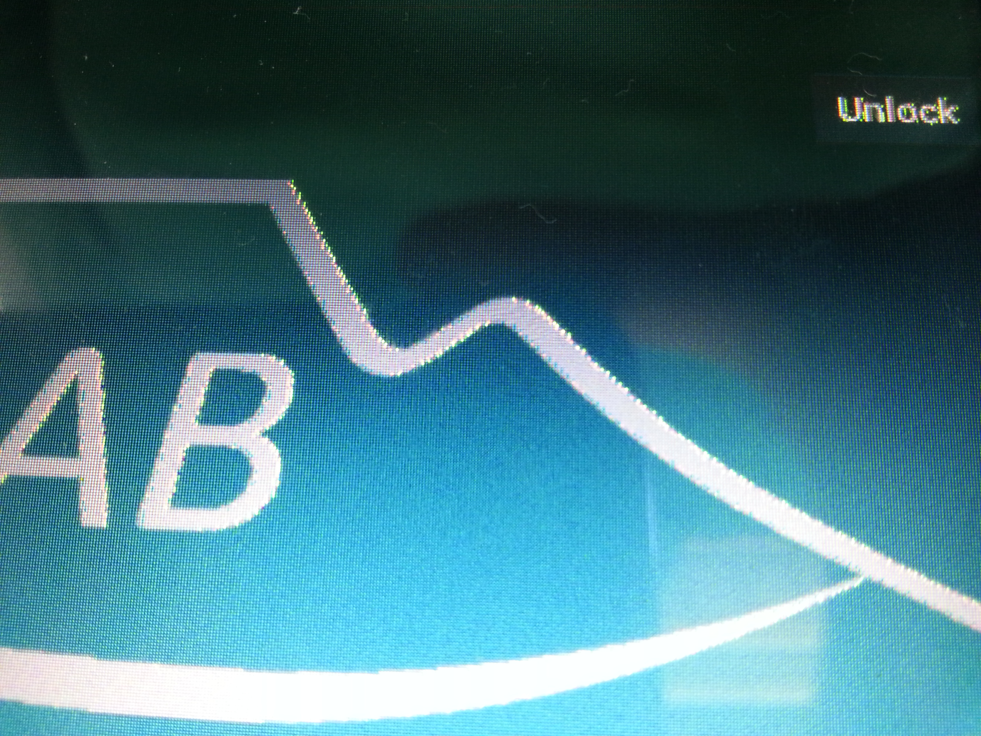
Hello, guys, I have a question about external LCD using DM8168 vout[0].

I connected VOUT[0]_R_CR[9]--VOUT[0]_R_CR[4] , VOUT[0]_G_Y_YC[9]--VOUT[0]_G_Y_YC[4] , VOUT[0]_B_CB_C[9]--VOUT[0]_B_CB_C[4] with 75LVDS84A transmitter to drive a 18bit LCD display.

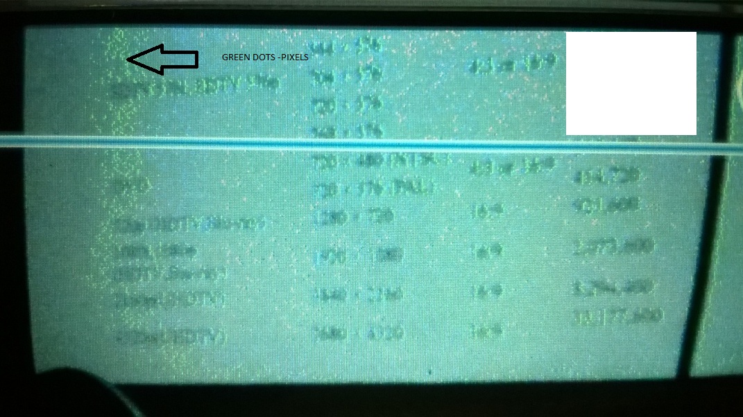
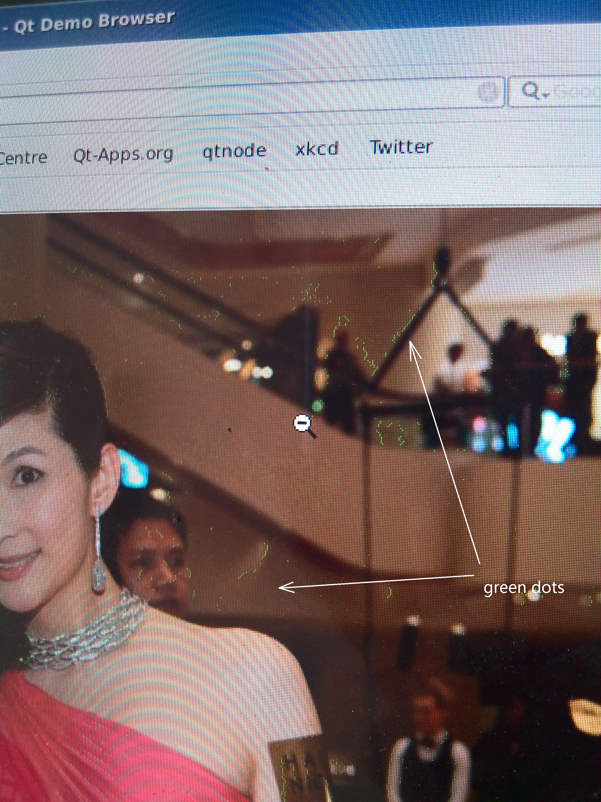
There are some green dots when the LCD displays some images, like follows:

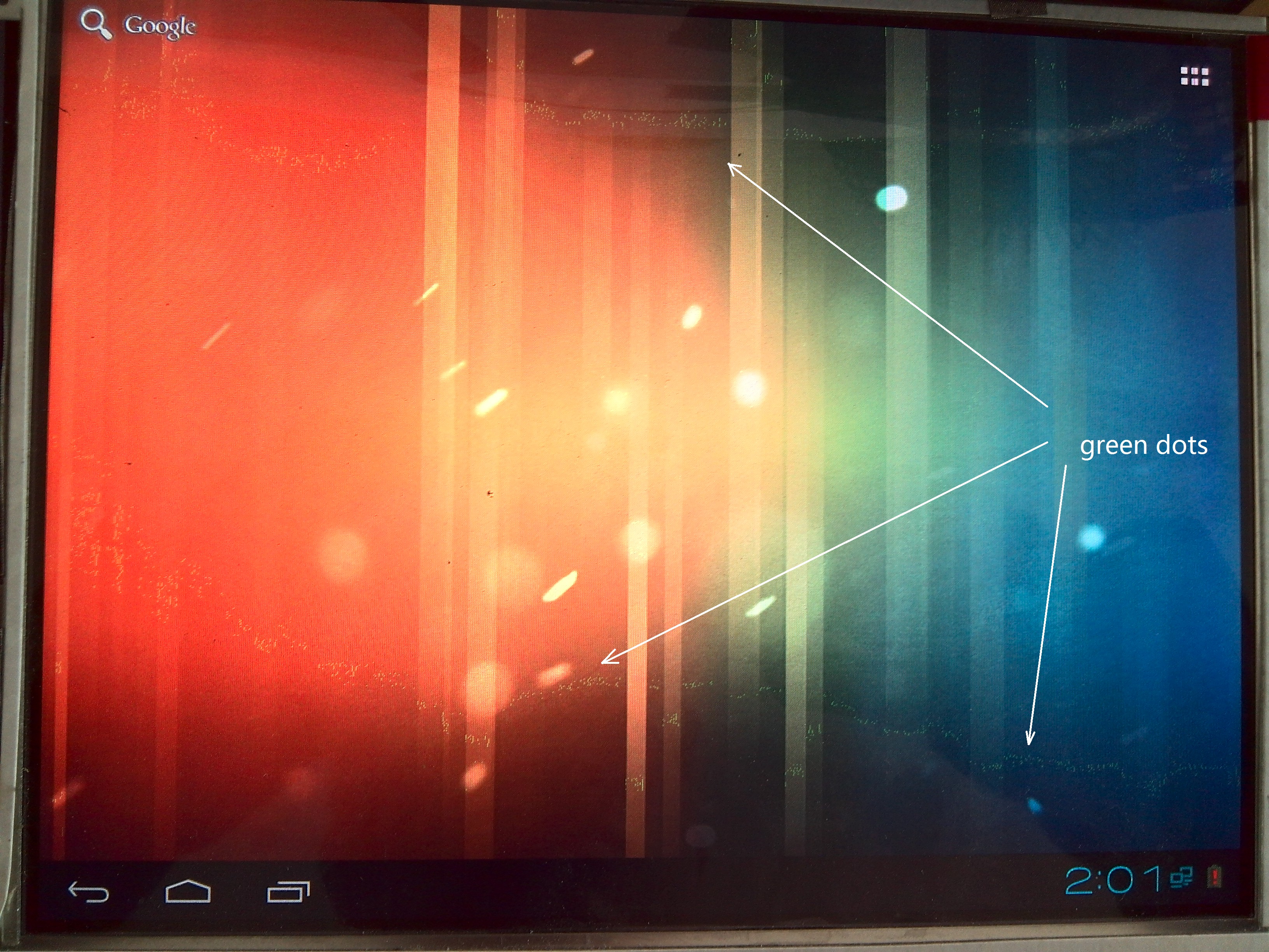
Anyone could help me?

Thanks,

  • Zeng,

    What is the resolution and your frame rate? Also can you share what is the final pixel clock that the display is being driven at?

  • This is a setup-hold violation in the timing between the DM8168 and the LVDS84A.

    If you look at oscilloscope captures of some of the data signals with respect to the clock close to the LVDS84A (trigger on the clock and enable persistence so that you get a clock-data eye diagram) you will see that data transitions are either distorted (closing up the eye) or the data transitions will be too close to the active edge of the clock.

    Examine the clock-data relationship and you will probably see that the setup-hold margins are insufficient for the 75LVDS84A (datasheet timing requirements on page 4).

    Often a solution to this issue is to either invert the source clock polarity or invert the sink capture clock polarity but in this case neither device has clock inversion control so you must either externally invert the pixel clock, or delay it somehow.

    To delay the clock you could either insert a high speed buffer or simply increase/decrease the clock PCB trace length by a few inches in order to change the relationship to active data edges.

    Make sure that all the data lines are very close in length too, which will ensure that the setup-hold window requirements are smaller.

    BR,

    Steve

  • HI, Thomas,

    Thanks for reply.

    According to the website:http://processors.wiki.ti.com/index.php/DM816X_AM389X_VPSS_Video_Driver_User_Guide#VPSS_Library:_display1

    My LCD display model is LP097X02. we use follows:

    echo 1024,768 > /sys/class/graphics/fb0/virtual_size
    echo 32 > /sys/class/graphics/fb0/bits_per_pixel
    echo 0 > /sys/devices/platform/vpss/graphics0/enabled
    echo 1:dvo2 > /sys/devices/platform/vpss/graphics0/nodes
    echo 0 > /sys/devices/platform/vpss/display1/enabled
    echo 1024x768@60 > /sys/devices/platform/vpss/display1/mode
    echo 100030,1024/260/480/320,768/16/6/10,1 > /sys/devices/platform/vpss/display1/timings
    echo 1 > /sys/devices/platform/vpss/display1/enabled
    echo 1 > /sys/devices/platform/vpss/graphics0/enabled

  • Hi Steve

    We are using a 24-bit parallel interface (RGB888) LCD panel in our DM8168 system. We observe "noise" on the LCD of some of our units (picture below). The LCD panel has been ruled out as the cause, as these "noisy" panels work flawlessly on our test jig (OEM supplied LCD driver board).

    The LCD datasheet (DLC0700BIG-1, 0383.DLC0700BIG-1 spec.pdf ) states that data is latched in on the falling edge of the pixel clock. From the DM8168 datasheet I gather that the video data on port VOUT[0] is also latched on the falling edge of VOUT[0]_CLK.

    Here is where things get weird: scoping the LCD signals in our system, I see that the colour data bits transition on the falling edge of the pixel clock. It is as if the pixel clock from the DM8168 is inverted (i.e., data is ready to be latched on the rising edge of the pixel clock).

    Below is a waveform capture that I made. It shows the pixel clock (yellow trace), R2 data bit (green trace) and B7 data bit (blue trace). All LCD signal tracks are constrained in length on the PCB, though not exactly the same length. B7 is the shortest track (38mm shorter than the pixel clock) and B7 is the longest track (4.4mm longer than the pixel clock). That equates to a maximum pixel clock to data bit delay of << 0.3ns, which is negligible considering the pixel clock has a period of 30ns.

    Have I misinterpreted the DM8168 datasheet i.t.o. the pixel clock polarity, or is the datasheet wrong? Furthermore, are there any options for inverting the pixel clock or delaying the data bits with half a cycle in software? The alternative would be to insert a hardware delay (longer clock track) or a fast inverting buffer. A hardware fix would off course be 2nd prize, due to the associated cost.

    Thanks for any help!

    Regards

  • Unfortunately it is a mis-interpretation of thaw the DM datasheet says. The datasheet does NOT say that you need to latch the data on the falling edge. It says that the outputs transition on the falling edge, which is exactly what you see.

    Green dots are 99.999999999% of the time timing violations due to capturing data on the wrong clock edge.

    So, unfortunately, unless your LCD has a capture clock edge polarity control you will need to either add trace length to your clock signal (effectively delay the clock), or insert a delay/inversion buffer on the clock line.

    Either way, make sure you do a full setup/hold timing analysis on the interface to make sure that you are within timing for all ranges of timing for both the DM and the LCD.

    BR,

    Steve

  • Hi Steve

    Thanks for your quick response, though it isn't good news for our current design it seems :(

    I will accept what you are saying, that the video data is only valid to be latched on the rising edge of the DM8168 pixel clock, which also agrees with what I saw on the scope.

    However, I still do not agree that this is what the datasheet says. Or perhaps I do not know how to interpret a simple timing diagram, in which case a bit of education from you to me may be required...

    From the DM8168 datasheet (page 265, 266), I get the following:

    Looking at Note No. 6 on the figure and table above, it is clearly stated that the delay time from the rising edge of the VOUT[0]_CLK signal to actual valid data being available is between 1.64ns to 4.85ns, which surely implies that the data will only be valid to be sampled / latched on the falling edge of the clock signal (or, conversely, data is not yet valid to be sampled / latched at the time of the rising clock edge, but only guaranteed to be so 4.85ns later).

    I would like to understand what is wrong with my simple interpretation of the above data, if you could be so kind.

    Thanks for your time!

    Regards

  • Hi Steve

    Update: I've "modded" in a high speed inverting buffer on the clock line and the display is now (liquid) crystal clear, with no noise or any other any other visual artifacts.

    Kind regards

  • Hmm, it looks like you might have found an error in the datasheet.

    I was thinking of the DM8148 where this was incorrectly documented but was fixed.

    I will need to get someone to look at this to determine why we see a difference.

    BR,

    Steve

  • Thanks again for your help Steve!

    Regards

    Ockie

  • Ockie,

    You are welcome. Sorry for the confusion.

    BR,

    Steve

  • OK, the datasheet is badly described.

    The timing is correct as listed, but ONLY for a 165MHz clock.

    The active edge is in fact the falling edge, but the timings listed are with respect to the rising edge and for a 165MHz clock, which is obviously not the correct way to describe the output timing, and will be wrong for any other clock frequency.

    This will be corrected in the next datasheet release.

    Again, sorry for the confusion.

    BR,

    Steve

  • Ahh... That makes sense, thanks for getting back!

    Regards

    Ockie

  • Hi ,

    Can anyone help us in one more similar issues of having these green pixels. We have camera preview on DM385 board with IPNC SDK. We have 5" LCD with 800x480 resolution screen. Tried almost all the config but no success.

    But the same LCD works fine on EZSDK.

    Can you please provide us few pointer on this issues.

    ykfs

  • This is a classic setup/hold violation.

    First you need to determine if this is a camera port capture issue or an LCD display issue.

    Often one quick way to check is to place your finger on the clock line to change the timing. Try placing your finger on the capture clock on an exposed pad if possible. If no exposed pads exist then clear the solder mask of the trace and press your finger on/off the exposed trace. If the image noise changes in any way (either gets better OR gets worse) then that is the clock which does not meet timing. If the capture clock does not show the issue then try the same test on the LCD display clock.

    BR,

    Steve

  • Hello Steve,

    We understand this but the issue is why LCD works nice with clear image with EzSDk on DM385.

    When we shift to IPNC RDK this issue pops up keeping the hardware same. Had there be any clock related issues then EZSDk should have showed the similar behaviour.

    Little confusion over here. By the way, we would try out these experiments.

    YK

  • I am not a software expert so cannot comment why one version is different to another. All I can say is that this is certainly a setup/hold violation either on the capture side or the display side.

    My guess is that this is a capture side issue since I don't believe the output display clock polarity can be changed.

    The input timing requirements are completely dependent on the externally connected device so it might be that one software release was initially designed for one capture device (e.g. TVP7002) whereas the other was designed for a different device (e.g. a CMOS sensor).

    BR,

    Steve