This thread has been locked.

If you have a related question, please click the "Ask a related question" button in the top right corner. The newly created question will be automatically linked to this question.

DM648 QDMA Transfer Completion

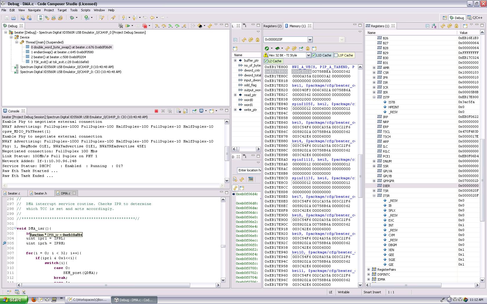
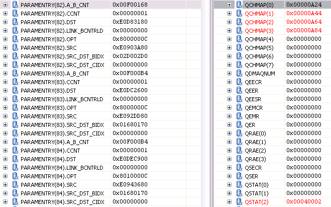
I spent a long time trying to get the ACPY3 API working but never got it going so now I am using the QDMA by directly writing into the QDMA registers. I can get the transfers working just fine except for two related problems. I can only get the 0th bit in IPR to go high when a transfer completes. If I set the TCC of the QDMA transfer to anything other than 0, IPR never changes. I have TCINTEN set high. Also, I am polling off of IPR because I cannot get an interrupt to trigger. Here are the steps that I go through to set up transfers and try to set up triggers...                        (everything here refers to a header file I created while referencing the data sheet)

        testQDMAch->params.SRC     = (uint)displayBuff->frame.pFrm.y;
        testQDMAch->params.DST     = (uint)tempY;
        testQDMAch->params.ACNT    = (uint)F_WIDTH;
        testQDMAch->params.BCNT    = (uint)F_HEIGHT;
        testQDMAch->params.SRCBIDX = ( int)F_WIDTH;
        testQDMAch->params.DSTBIDX = ( int)F_WIDTH;
        testQDMAch->params.SRCCIDX = ( int)0;
        testQDMAch->params.DSTCIDX = ( int)0;
        testQDMAch->params.CCNT    = (uint)1;
        testQDMAch->params.BCNTRLD = (uint)0;
        testQDMAch->params.LINK    = (uint)0;
       
        testQDMAch->params.OPT.ITCCH      = EDMA_OPT_ITCCH_DIS;
        testQDMAch->params.OPT.TCCH       = EDMA_OPT_TCCH_DIS;
        testQDMAch->params.OPT.ITCINT     = EDMA_OPT_ITCINT_DIS;
        testQDMAch->params.OPT.TCINT      = EDMA_OPT_TCINT_EN;
        testQDMAch->params.OPT.TCC        = EDMA_OPT_TCC( myTCC /*or whatever TC code I want*/);
        testQDMAch->params.OPT.TCCMODE    = EDMA_OPT_TCCMODE_NORM;
        testQDMAch->params.OPT.FWID       = EDMA_OPT_FWID_8b;
        testQDMAch->params.OPT.STATIC     = EDMA_OPT_STATIC_EN;
        testQDMAch->params.OPT.SYNCDIM    = EDMA_OPT_SYNCDIM_AB;
        testQDMAch->params.OPT.DAM        = EDMA_OPT_DAM_INC;
        testQDMAch->params.OPT.SAM        = EDMA_OPT_SAM_INC;
       
        testQDMAch->trigger = PARAM_SRC;

I have a function that goes through and actually writes all those options into the registers, and a function that enables the QDMA channel and rewrites the trigger word to start the transfer. But the transfer works fine...

I poll for the completion using...

 while((IPRL & 0x1<<myTCC) != 0x1<<myTCC){}
        ICRL = 0x1<<myTCC;

If myTCC = 0 then everything works fine. However, if myTCC != 0 then I get stuck in the while loop.

Onto interrupts... Here is the code in my TCF to try to get a HWI to fire.

bios.HWI.instance("HWI_INT4").interruptSelectNumber = 24;
bios.HWI.instance("HWI_INT4").fxn = prog.extern("DMA_isr");
bios.HWI.instance("HWI_INT4").useDispatcher = 1;

Here is how I am setting the IER (0x02A01050)...

if(hChannel->params.OPT.TCC > 31)
        IESRH = 0x1 << (hChannel->params.OPT.TCC - 32);
    else
        IESRL = 0x1 << (hChannel->params.OPT.TCC);

And my ISR...

void DMA_isr(){
    int i;
    uint iprl = IPRL;
    uint iprh = IPRH;
   
    for(i = 0; i < 32; i++){
        if(iprl & 0x1<<i){
            /*big switch statement to act on each particular bit that is set*/
            ICRL = 0x1<<i;
        }
        if(iprh & 0x1<<i){
            /*big switch statement to act on each particular bit that is set*/
            ICRL = 0x1<<i;
        }
}

I put a breakpoint on the first line of my ISR so I know if it goes in there and it never does.

Does anybody see what I might be doing wrong? If I left any details out please let me know I will include those.

  • Here is a screen shot showing my interrupt vector table. I am using HWI4 but it doesn't seem to contain the address of DMA_isr()

  • The EDMA User Guide has a footnote saying to make 32-bit accesses to the Parameter RAM whenever possible.  I believe the way you've broken up the accesses (e.g. ACNT and BCNT as separate accesses) as well as the bit-fields for OPT are potentially causing problems.  This might be tied into the odd issues you're seeing with interrupts.

    Since you're using the BIOS dispatcher, the interrupt vector table will branch to the dispatcher, not to your ISR.  That's fine.  At the end of your ISR you should write IEVAL=1.  That's obviously not causing this issue, but could cause you to miss an interrupt at run-time (once you get the interrupts working!).

  • My function that writes the settings to the actual registers writes them as 32-bit accesses by way of macros such as...

    PARAM_B_A_CNT_(paramNum) = PACK_B_A_CNT(hChannel->params.BCNT, hChannel->params.ACNT);

    where...

    #define PARAM_BASE                      (0x02A04000) /* DM648. Check address for other devices. */
    #define PARAM_(x)                            (PARAM_BASE + x*0x20)
    #define PARAM_B_A_CNT_(x)        *((volatile unsigned int *)(PARAM_(x) + 0x08))

    #define PACK_B_A_CNT(frm, ele)   (uint)(((frm-1)<<16) + ele)

    That should be correct, right?

    If I turn off the BIOS dispatcher, will it correctly branch to my ISR?

  • Ok, I just misunderstood your code.  I thought your pointer/structure was directly modifying the Parameter RAM.

    Why are you doing frm-1 instead of frm?  That doesn't look right, but it does look to be a proper 32-bit access.

    I wouldn't recommend turning off the BIOS dispatcher as you'll likely create new issues.  There's no issue with the dispatcher.  The issue is purely that the interrupt has somehow not been triggered.

  • Yeah, I just have that pointer/structure to make it easier to modify and keep track of the settings.

    I thought I saw somewhere that if BCNT = n then number of arrays is n-1. I can't find where I saw it though... Should it just be frm? Are there any other bits that need to be set for an interrupt to occur? and have I correctly set it up in the TCF so that it branches to DMA_isr()?

    Also, what is the purpose of BCNTRLD in general?

  • Daniel Nadeau said:

    I thought I saw somewhere that if BCNT = n then number of arrays is n-1. I can't find where I saw it though... Should it just be frm?

    It should just be frm.  The total number of bytes transfered for a parameter set is ACNT*BCNT*CCNT, i.e. there is no "num-1" business in EDMA3.

    Daniel Nadeau said:

    Are there any other bits that need to be set for an interrupt to occur? and have I correctly set it up in the TCF so that it branches to DMA_isr()?

    Are you using any of the shadow region stuff (DRAEn)?  If not, then the global interrupt you selected in the tcf looks like the right value.  It looks like you've configured things correctly (TCC, TCINTEN, EDMA.IER).  Your BIOS configuration should take care of the rest.

    Are you enabling the CPU IER?

    Daniel Nadeau said:

    Also, what is the purpose of BCNTRLD in general?

    The BCNTRLD is pertinent only for A-synchronized transfers.   In this scenario the channel controller decrements BCNT after every sync event / transfer.  Once BCNT reaches zero then it decrements CCNT and reloads BCNT from BCNTRLD.

    In the case of AB-synchronized transfers then for each sync event that comes in the EDMA will transfer ACNT*BCNT bytes and it will decrement CCNT.  In this case since BCNT never gets decremented the BCNTRLD field is a "don't care".

  • I pretty sure I'm not using any shadow region stuff. What is that exactly? I've seen it mentioned many times but never really found a good explanation.

    I think the CPU IER might be the problem. I thought setting the EDMA.IER (0x02A01050) took care of all that. I am looking through documents to find the address and how to deal with the CPU IER. Could you point me in the right direction?

  • The shadow regions are meant for multi-core DSPs such that each core can "own" some of the resources.  For example, in an ARM+DSP system, you would not want both the ARM and the DSP to get interrupted for the same completion event.  In that case you'd end up with a situation where for example the DSP would say, "Yep, that's one of my events" and would process it while the ARM would say, "I don't recognize that TCC" and it would have been interrupted for nothing.  For this scenario one "shadow region" is routed to the ARM and the other to the DSP.  That way the ARM only gets interrupted for its channels and the DSP only gets interrupted for its channels.  The EDMA3 supports up to 8 shadow regions so this could work in up to an 8-core device.

    The CPU IER register does not actually have an address.  A special instruction is used to access it.  The easiest thing is to just use a BIOS API.  This wiki mentions how:

    http://wiki.davincidsp.com/index.php/Setting_up_interrupts_in_DSP_BIOS

    So in your case you'd do something like:

    #include <c64.h>
    C64_enableIER (C64_EINT14);
  • That got the interrupt working! Thanks. Now, do you have any idea why I can only get a TCC = 0 to work?

    Also, I think you meant C64_EINT4 instead of C64_EINT14.

  • Quick test -- comment out your code that sets the EDMA IER bits.  Then let your QDMA transfer run and look if any IPR bits ever get set.


  • I did that and the TCC of 0 still worked. I tried other TCCs and it didn't work. So I thought maybe it wasn't even my transfer that was setting IPR.0, I put another polling while loop before my transfer and it never breaks out of it. Therefore my transfer must be setting the IPR bit, which is odd because I am not setting the EDMA IER bit.

  • Please copy/paste the hex values directly from memory that have been programmed into the Parameter RAM set.  Please also copy/paste the QCHMAPn values.

    Can you post the entire file that programs the EDMA/QDMA?  I might spot something if I see it all.  Are you programming QCHMAPn prior to the Parameter RAM programming?  Are you sure you're writing to the trigger word last?

  • I am using QDMA to split up a screen to show 4 video inputs. I am using 3 channels, one for each of Y, CB, and CR. Then reusing the channels for putting each video input into their respective quadrants. Since I am submitting all 3 transfers to the same transfer controller queue ( QDMAQNUM = 0;) , I only have the TCINT enabled on the last transfer submitted.


    So here is basic flow of how I am setting things up...

    In main...

        DMA_params_init();


    In my task doing the QDMA transfer...


        DMA_channel *PQ_QDMAchannels[3];

        DMA_init_QDMA_channels();

        DMA_grant_QDMA_channel(&PQ_QDMAchannels[0]);
        DMA_grant_QDMA_channel(&PQ_QDMAchannels[1]);
        DMA_grant_QDMA_channel(&PQ_QDMAchannels[2]);

        off = offset[quadrant]; //offset to the first element of respective quadrant
       
        channels[0]->params.SRC       = (uint)inputBuffPtr  ->frame.pFrm.y;
        channels[0]->params.DST       = (uint)displayBuffPtr->frame.pFrm.y  + off;
        channels[0]->params.ACNT      = (uint)Y_WIDTH;
        channels[0]->params.BCNT      = (uint)Q_HEIGHT;
        channels[0]->params.SRCBIDX   = ( int)Y_WIDTH*2;
        channels[0]->params.DSTBIDX   = ( int)F_WIDTH;
        channels[0]->params.OPT.TCINT = EDMA_OPT_TCINT_DIS;   
        channels[0]->trigger = PARAM_SRC;
        DMA_setup_QDMA_transfer(channels[0]);
       
        channels[1]->params.SRC       = (uint)inputBuffPtr  ->frame.pFrm.cb;
        channels[1]->params.DST       = (uint)displayBuffPtr->frame.pFrm.cb + off/2;
        channels[1]->params.ACNT      = (uint)C_WIDTH;
        channels[1]->params.BCNT      = (uint)Q_HEIGHT;
        channels[1]->params.SRCBIDX   = ( int)(C_WIDTH + C_OFFSET)*2;
        channels[1]->params.DSTBIDX   = ( int)(F_WIDTH/2);
        channels[1]->params.OPT.TCINT = EDMA_OPT_TCINT_DIS;
        channels[1]->trigger = PARAM_SRC;
        DMA_setup_QDMA_transfer(channels[1]);
       
        channels[2]->params.SRC     = (uint)inputBuffPtr  ->frame.pFrm.cr;
        channels[2]->params.DST     = (uint)displayBuffPtr->frame.pFrm.cr + off/2;
        channels[2]->params.ACNT    = (uint)C_WIDTH;
        channels[2]->params.BCNT    = (uint)Q_HEIGHT;
        channels[2]->params.SRCBIDX = ( int)(C_WIDTH + C_OFFSET)*2;
        channels[2]->params.DSTBIDX = ( int)(F_WIDTH/2);
        channels[2]->params.OPT.TCC = EDMA_OPT_TCC(0);   
        channels[2]->trigger = PARAM_SRC;
        DMA_setup_QDMA_transfer(channels[2]);
       
        DMA_start_QDMA_transfer(channels[0], (uint)inputBuffPtr->frame.pFrm.y );
        DMA_start_QDMA_transfer(channels[1], (uint)inputBuffPtr->frame.pFrm.cb);
        DMA_start_QDMA_transfer(channels[2], (uint)inputBuffPtr->frame.pFrm.cr);


    A channel's QEER is always disabled until inside my start function when it gets set right before i rewrite my trigger word and then it is immediately disabled again.

    Here is a screenshot of my PaRAMs and QCHMAPn. I am using channels 1-3 with PaRAMs 82-84

    I am actually writing into the PaRAM then mapping the QDMA channel to the PaRAM. My DMA_init_QDMA_channels() decides which PaRAM will be used by each channel, then the DMA_setup_QDMA_transfer() actually writes into QCHMAPn after the PaRAM has been filled out.


    DMA.zip
  • Will you please open a memory window to address 0x02A0_4A40 and take a screenshot similar to the one above?  I'd like to be able to rule out errors that could arise from defining the parameter sets incorrectly in your code.

  • In order for TCC to cause a bit to be set in IPR/IPRH you need to set the TCINTEN bit.  For parameter sets 82 and 83 you will never know when they complete as it is currently programmed.  For parameter set 84 it will set bit 0 of IPR when it is complete since TCC=0.

    As long as TCINTEN is set, then you should be able to program OPT.TCC to any value and see the corresponding bit in IPR/IPRH set upon completion of the transfer.

  • Brad Griffis said:
    For parameter sets 82 and 83 you will never know when they complete as it is currently programmed.

    I thought that since they are all loaded into the same FIFO queue that 83 would not start until 82 was finished and 84 would not start until 83 was finished. Thus only requiring an interrupt on the completion of 84, since i need them all to complete before I do anything else.

    I am currently having trouble getting my EVM running again (occasionally it, and/or the emulator decide they don't want to work and eventually decide otherwise), so I will have to wait until after the New Year to post that screen shot. I'm pretty sure I have confirmed that the memory was getting set how I expected, but I will check again and post the screenshot as soon as I get it running again.

    Thanks again for the help.

  • Daniel Nadeau said:

    I thought that since they are all loaded into the same FIFO queue that 83 would not start until 82 was finished and 84 would not start until 83 was finished. Thus only requiring an interrupt on the completion of 84, since i need them all to complete before I do anything else.

    Sorry, you're right.  Since each Parameter Set maps to a different QDMA channel you are able to initiate a transfer on each channel and be guaranteed that they will complete in order.

    Happy New Year!

  • Here is the screenshot of the memory locations

  • Let me make sure I understand where you're at right now.  So at one point you could not generate a CPU interrupt, but I believe that was due to the fact that CPU.IER was not configured properly, right?

    For the purpose of debug, please try the following:

    1. Comment out the line of code that sets the appropriate bit in EDMA.IER.
    2. Run your code "as is" such that TCC=0.  You should see IPRL.BIT0 set at the completion.
    3. Re-run the test this time with TCC=1.  You should now see IPRL.BIT1 set at the completion.

    If item 3 doesn't work please check to see what has been transferred to determine if the QDMA transfer was successful, i.e. was the destination updated in its entirety.

    Brad

  • I commented out the setting of EDMA.IER and polled off of IPRL.BIT0. The bit got set correctly and I confirmed that the transfer completed. When I changed the TCC to 1, IPRL.BIT1 never got set and so the program got hung up in my polling while loop. I paused it and looked at the memory and the transfer was successful. So the transfer is taking place but the IPR isn't getting set.


    Brad Griffis said:
    So at one point you could not generate a CPU interrupt, but I believe that was due to the fact that CPU.IER was not configured properly, right?

    Yes, that is correct. I know have no problem generating a CPU interrupt using TCC = 0;

  • Can you make a stripped down test case that I can reproduce on the DM648 EVM?

  • I found two major issues with my code. I can now get the IPR bit to be set for TCC's other than 0 but for some reason cannot get the interrupt to fire. If I change the TCC back to 0 the interrupt fires just fine.

    For completeness, here are my two issues I had in my code...

    The first one was how I was setting EDMA.IER:

        if(hChannel->params.OPT.TCINT == EDMA_OPT_TCINT_EN){
            if(hChannel->params.OPT.TCC > 31)
                IESRH = 0x1 << (hChannel->params.OPT.TCC - 32);
            else
                IESRL = 0x1 << (hChannel->params.OPT.TCC);
        }

    hChannel->params.OPT.TCC is actually the 32bit field with the value already shifted to the left by EDMA_OPT_TCINT_SHIFT. I did this to make it easier to actually set the OPT field in the PaRAM, but forgot that I did it that way. The following is the fix:

        int channel_tcc = hChannel->params.OPT.TCC >> EDMA_OPT_TCC_SHIFT;
          
        if(hChannel->params.OPT.TCINT == EDMA_OPT_TCINT_EN){
            if(channel_tcc > 31)
                IESRH = 0x1 << (channel_tcc - 32);
            else
                IESRL = 0x1 << (channel_tcc);
        }


    The second problem was caused by a misread of the EDMA3 User Guide (SPRUEL2B). The TCC is supposed to be in bits 12-17 of the OPT register and I set my EDMA_OPT_TCC_SHIFT to 17 by accident. So when TCC was zero it wasn't a problem but when I set it to anything else I shifted the bits up too high.

    Now I just need to work out why my interrupt isn't firing... I can't remember if I had to set something special for each TCC...

  • Great news!  Are you positive that you NEVER get the interrupt?  Whether you're using TCC=0 or TCC=1, etc the interrupt functions exactly the same, i.e. it's a shared interrupt.

    Since you were already getting the interrupt I don't see how the fixes you made would "break" the interrupt.  A couple things to check in your ISR:

    • You need to clear the IPR bit as you service it.
    • Write IEVAL=1 before exiting the ISR.

    The above steps would fix the case where you get it once only.  Perhaps that's what you mean (or maybe you set the breakpoint after it had already run).

    Brad

  • Ok, thanks. I am pretty sure I am not getting the interrupt. I thought they were on the same interrupt and that's why I confused when it didn't fire. I will confirm whether or not its firing and try your suggestions on Monday. We are getting out early today do to the inclement weather in Atlanta.

  • The interrupts were firing... At the beginning of my ISR I stored IPR into ipr but I masked it with ipr & 0x1 for when I was just trying to interrupts working. So now I have interrupts firing on all TCCs. Thanks alot! 

    What does IEVAL = 1 do?

    I have one last question about EDMA transfers... If I were to use EDMA cahnnel 8 which is mapped to PaRAM 8 and I linked it as follows: 8 -> 100 -> 101 -> NULL

    From what I have read, I am under the understanding that PaRAM 100 will get copied into 8, then 101will get copied into 8, then NULL will get copied into 8. So at the end of the transfer 8 will be equal to the NULL PaRAM, correct? But, will 100 and 101 still remain intact? Also, say 8 is equal to the NULL PaRAM except that it was linked to 100. If I started a transfer with PaRAM 8, would it be the same as if I was just starting it with PaRAM 100?

  • Daniel Nadeau said:

    What does IEVAL = 1 do?

    It causes the EDMA interrupt to the core to be re-evaluated to see if there are still any pending interrupts.  Otherwise if an interrupt came in after you read IPR but before you cleared the corresponding bits you would never get another interrupt from the EDMA.  In other words, you would probably see EDMA run for some amount of time and then it would suddenly stop.  This is documented in the EDMA User Guide if you want to know more.

    Daniel Nadeau said:

    I have one last question about EDMA transfers... If I were to use EDMA cahnnel 8 which is mapped to PaRAM 8 and I linked it as follows: 8 -> 100 -> 101 -> NULL

    From what I have read, I am under the understanding that PaRAM 100 will get copied into 8, then 101will get copied into 8, then NULL will get copied into 8. So at the end of the transfer 8 will be equal to the NULL PaRAM, correct?

    Correct.

    Daniel Nadeau said:

    But, will 100 and 101 still remain intact?

    Yes, 100 and 101 would not be modified in any way for this scenario.  Their contents are copied into set 8.

    Daniel Nadeau said:

    Also, say 8 is equal to the NULL PaRAM except that it was linked to 100. If I started a transfer with PaRAM 8, would it be the same as if I was just starting it with PaRAM 100?

    Why would you ever do this?  No, it wouldn't work that way because if an event occurs for a NULL parameter entry then an error is flagged.  The DM648 has a DCHMAP register where you can just directly map channel 8 to be associated with PaRAM 100 if you want.

    This thread has gotten quite long.  If you have further questions please start a new thread.  Thanks.