This thread has been locked.

If you have a related question, please click the "Ask a related question" button in the top right corner. The newly created question will be automatically linked to this question.

TMS320C5515 timer 1 & 2 conflicts/misses

I'm trying to create a program that uses timer0 to fire off an interrupt every 70 microseconds and timer1 to fire off an interrupt every 60 microseconds. I'm using a 100Mhz system clock with a prescaler of 4 to end up with timer ticks being worth 40nS. In addition, autoreload is enabled for both timers.

The problem is, that despite section 1.6.3 of SPRUFX5D (System Guide) stating that if two timer interrupts occur simultaneously and the ISR decides to service one at a time (subsequently clearing the appropriate flag in TIAFR one at a time, the ISR should immediately fire again to service the remaining timers. 

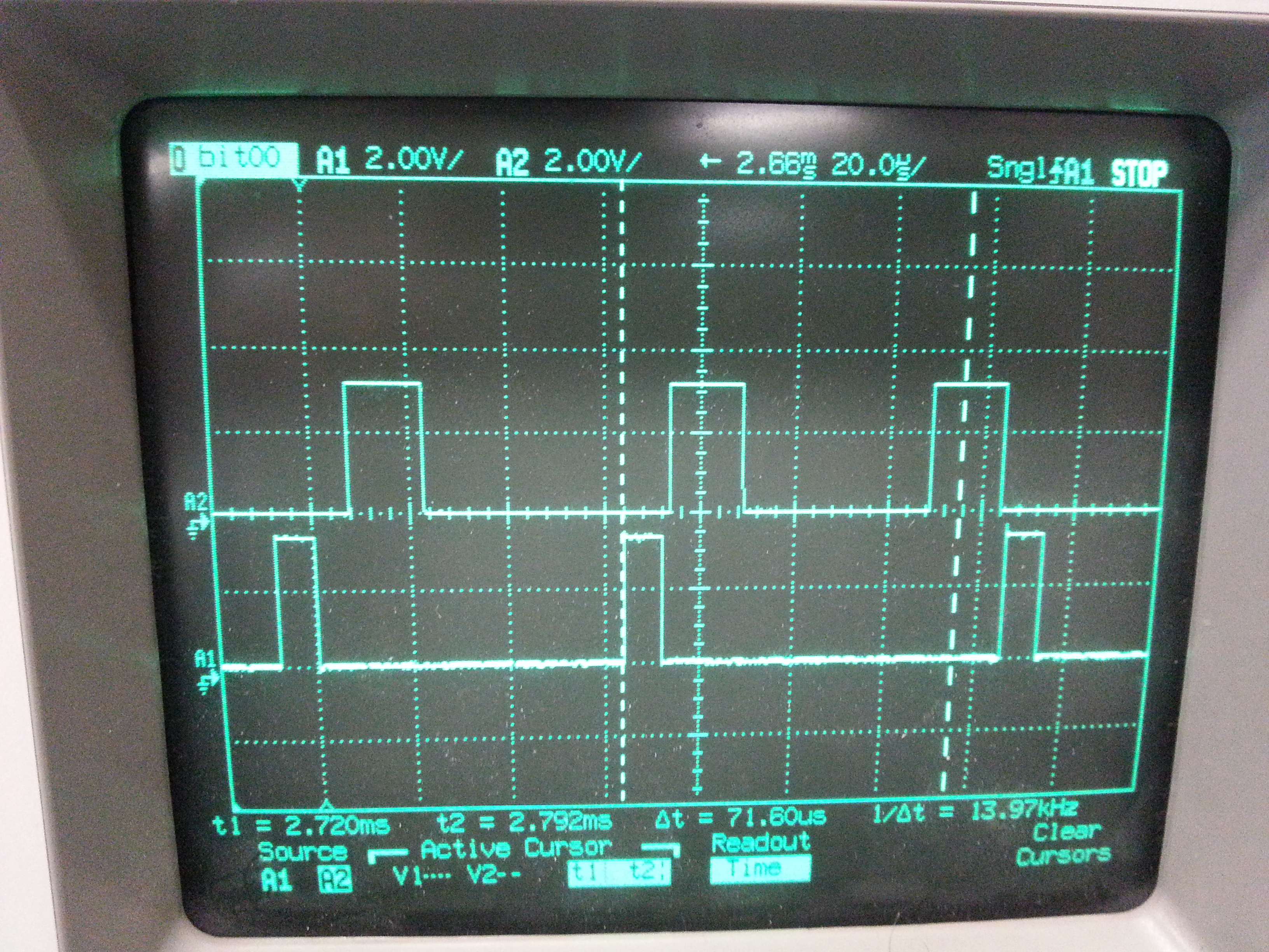
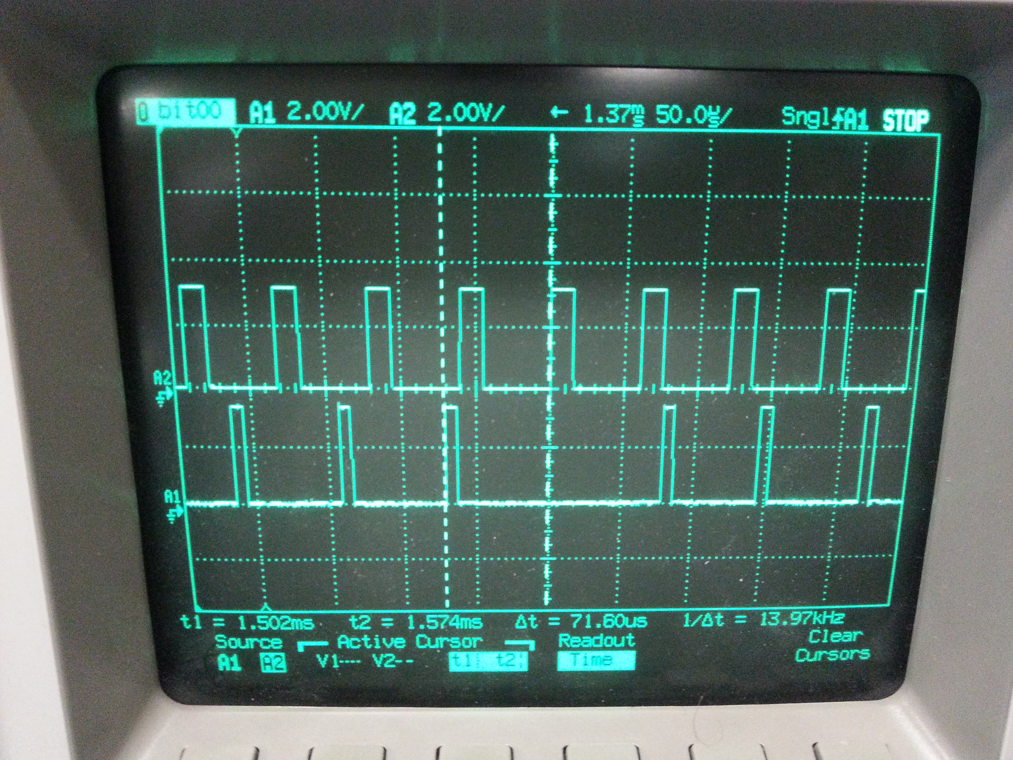
What I'm seeing is that my 70uS timer 0 is periodically being missed. Specifically, the code under the conditional statement seeing if TIAFR bit 0 is set is not executing. I've verified this by toggling a GPIO line in the ISR and periodically watching the missed pulses on an o-scope. In addition, if I increase the frequency of timer1, the likelihood increases that the timer0 code won't execute. Subsequently, lowering the timer1 frequency decreases the misses of timer 0.

The following is my ISR, with the non relevant parts removed. It seems that in the scenarios where timer 0 & 1 are firing simultaneously, the timer 0 flag isn't getting set/staying latched in the TIAFR or perhaps the ISR isn't being re-entered upon completion of timer 1 execution.

Any and all assistance is greatly appreciated. It's not clear, based on the documentation, why timer0 shouldn't be serviced each and every time in this ISR. I would at least expect to see some skew in the pulses if my timer1 code was too long, but not a complete miss of timer0.

Thanks!

Adam

-----------------------------------------------------------------------------------------------------------------------------------------------------

#define TIM_TIAFR_TIM0_BIT 0x0001
#define TIM_TIAFR_TIM1_BIT 0x0002

#define REG_TIAFR *(volatile ioport uint16_t*)(0x1c14)

interrupt void timer_isr(void)
{
     uint16_t register_value = 0;

     register_value = REG_TIAFR;

     if(register_value & TIM_TIAFR_TIM0_BIT)
     {

/* Clear Timer 0 flag in Timer Aggregate flag register*/

REG_TIAFR |= TIM_TIAFR_TIM0_BIT;

 GPIO_IODATAOUT1 |= 0x0004;                           //For debugging

//******* do 1uS of work (setting flags, updating variables, etc) *******

GPIO_IODATAOUT1 &= ~0x0004;                        //For debugging

     }

     if(register_value & TIM_TIAFR_TIM1_BIT)

    {

/* Clear Timer 1 flag in Timer Aggregate flag register*/
REG_TIAFR |= TIM_TIAFR_TIM1_BIT;

//******* do 1uS of work (setting flags, updating variables, etc) *******

     }

}

  • I've added some o-scope captures to illustrate the problem.

    In the attached images, the top pulses represent a GPIO pin being toggled in timer 1. The bottom pulses represent a GPIO pin being toggled in timer 0.

    Timer 0 is setup to fire every 71.6 uS. Timer 1 is setup to fire every 60.5uS.

    "Expected Behavior.jpg" illustrates a scenario where timer 0 (bottom waveform) can be seen executing every 71.6uS. It can be seen that timer 1 executes and blocks (a little longer than the 1 uS I listed in the comments of the first post), causing a delay in the 3rd firing of timer 0, as expected. Based on the way the ISR is written, this shows that the timer 1 routine executed, the ISR exited, and was immediately entered again to service the pending timer0 interrupt.

    "Missed Interrupt.jpg" illustrates a scenario where both timer 0 (bottom waveform) and timer 1 are both executing. It can be seen that the 4th pulse of timer 0 is missing. If one looks at the cursors, it can be seen that the missed firing of timer 0 occurred at the exact same time when timer 1 begins
    execution. I would expect a similar result as shown in "expected behavoir.jpg" where timer 1 would first execute, the ISR would exit and be re-entered,and then the timer 0 code would be executed.

    I've also made observations where timer 1 is missed when the timer 0 interrupt fires off at roughly the same time.

    It appears the ISR is not being re-entered when timers 0 & 1 expire simultaneously.

    I'm hoping I'm doing something wrong with my ISR setup, not some low level time bug within the DSP. I see the TINT bit of IFR0 is self clearing when the ISR is entered. I would think this bit needs to set again if two timer interrupts go off at the same time in order for the ISR to be re-entered.

    Expected Behavior:

    Missed Interrupt:

  • Hello Adam,

      Looks like you are clearing both the interrupts in your ISR.

    The ISR can choose to service both timer interrupts or only one-at-a-time. If the  ISR services only one of them, then it should clear only one of the TIAFR flags and upon exiting the ISR, the CPU will immediately be interrupted again to service the second timer flag.

    Hope this helps.

    Regards

     Vasanth


  • I'm afraid I don't understand Vasanth. I'm only clearing the respective TIAFR bit only after meeting the condition in each IF statement. Therefore, if I enter this ISR and both TIM0 and TIM1 flags are set in the TIAFR register upon entering, then they both are serviced because of the way the if statements are setup. If only timer0 bit is set, then only timer0 is cleared in the TIAFR.

    The clearing of the respective TIAFR bits only occur as needed. If I understand your response correctly, your stating that that I'm clearing both TIAFR bits every time this ISR is called.

  • What is the register_value you read before you service the respective Timer ISR.

    Also I would like yo to check the INTM bit status : Below is the information in INTM :

    Before executing an interrupt service routine (ISR) triggered by an INTR #5 instruction, by the RESET instruction, or by a hardware interrupt source, the CPU automatically sets the INTM bit to globally disable the maskable interrupts. The ISR can re-enable the maskable interrupts by clearing the INTM bit.

    A return-from-interrupt instruction restores the INTM bit from the data stack

    More information on the INTM can be found in the Link swpu073e

    Please confirm on the above.

    Regards

     Vasanth


  • The first step in the execution of the SIR is to read the Timer Interrupt Aggregation Flag Register (TIAFR, 0x1C14) and check bits 0 and 1 to determine source of the timer interrupt .

    In regards to your second question, I set a breakpoint at the first line of the timer ISR and observed the INTM bit set to one. This confirms SWPU073. Upon leaving the ISR and returning execution to the main loop, I observed the INTM bit restored to 0.

    However, I was able to fix my problem by changing the way I write a 1 to the TIAFR to clear the respective flag.

    The previous code (as shown above) used a logical OR to set the bit (TIAFR |= 0x01). Upon looking into the CSL code, I observed the value use to set the respective bit was directly written into the register (TIAFR = 0x01;). It's somewhat counter intuitive to me to overwrite a register value instead of ORing in the bit I want to set, but I understand I can get away with it since this register is not effected with writes of zero to any bit.

    I guess there was some kind of timing issue going on since the OR line of code causes a read and write of the memory location while the write is just that, a direct write. 

    Any thoughts why I can't get away with the OR to set that bit?

  • Below is where I think the issue could be:

     Assuming that the first step in your ISR you read value of 0x01 (register_value) from TIAFR , then started executing first if condition but before you clearing the Timer0 interrupt , say Timer1 Interrupt occurred. In this case OR operation would clear both the interrupt. So the second if condition will not execute and also no interrupt gets generated as your INTM bit will be set inside an ISR.

    • So from my point of view, right way to implement is not to use OR function but just clear that particular interrupt. Also you could configure INTM bit to 0 when you enter interrupt.

    Hope the above explanation justifies the issue you had faced.

  • Indeed it does. The OR condition works 99% of the time, it doesn't work in that small window where the DSP sets the bit between the ISR firing and the time I perform the OR.

    Thank you again for your diligence in following through with this question!