This thread has been locked.

If you have a related question, please click the "Ask a related question" button in the top right corner. The newly created question will be automatically linked to this question.

C6678 PG1.0 vs PG2.0 Boot ROM functionality

Other Parts Discussed in Thread: TMS320C6678

Hi Champs,

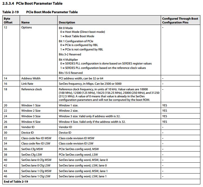
looking at the new bootlader User's Guide SPRUGY5C it seems that the boot parameter table functionality has disappeared.

While in SPRUGY5A the boot parameter table functionality is explained in detail. See e.g. Section 3.4, Table 3-12 PCIe Boot Parameter Table.

Does this mean C6678 PG2.0 Boot ROM does not support PCIe Boot Parameter Table anymore or does still work like described in SPRUGY5A?

Kind regards,

one and zero

  • Hello,

    according to this topic:

    what is the best way to boot a C6678 device for PCIe where the SUBSYS_ID & SUBSYS_VEN_ID has to be set before the original boot?

    Best Regards,
    Bernd

  • one and zero,

    The boot parameter table functionality is now documented in the TMS320C6678 device datasheet: http://www.ti.com/lit/gpn/tms320c6678. 

    The PCIe boot parameter table in particular is in section 2.5.3.4 and table 2-19.

    Thanks,

    Jason Reeder

  • Hi Bernd,

    I believe the only way to modify SUBSYS_ID & SUBSYS_VEN_ID before the actual PCIe boot is if you go through an I2C boot first and then enter the PCIe boot.

    Jason if you have a better idea please let us know. Or of course anyone else who wants to jump in ...

    Kind regards,

    one and zero

  • Bernd,

    one and zero is correct. As you can see from the PCIe boot parameter table only the window size is configurable through the configuration pins (AKA boot strap pins). This means that on a PCIe first stage boot this is the only portion of the boot parameter table that you can alter before the PCIe boot begins.

    If you would like to modify the vendor ID or the device ID using the boot parameter table you would need to use a different boot mode to transfer in the PCIe boot parameter table with the configurations that you would like and then re-enter the boot process to use the new table.

    Here is the PCIe boot parameter table from the datasheet:

  • Hello Jason,

    thanks for your answer. Therefore I'll use an I²C-Boot like this:

    -boot device field:
                    -mode is I²C master boot (0x28)
                    -parameter index: index * 0x80 should be address for I²C boot parameter table, isn't it?
                    -other parameters are clear

    -use a I²C boot parameter table:
                    -option to boot config mode
                    -boot dev address points to boot config table
                    -what is local address used for?
                    -next dev addr points to boot parameter table for PCIe (see below)
                    -other parameters are clear

    -use a I²C boot config table (e.g. direct behind I²C boot parameter table in I²C)
                    -change SUBSYS_ID
                    -change SUBSYS_VEN_ID
                    -jump to PCIe boot parameter table

    -use a PCIe boot parameter table (e.g. direct behind I²C boot config table in I²C)
                    -Option has to be:
                                    -boot table boot mode?
                                    -PCIe is configured by RBL?
                    -configure window sizes, etc.
                    -other parameters are clear

    Now I have the following questions:
    -the orange parts above
    -how can these tables be created by me and written to I²C-EEPROM?

    I think I have to use the tools like b2i2c.exe and the eepromwriter_evm6678l.out, but I'm not able to find any documentation how to create the table, convert it and write to the eeprom.


    Thanks for clarifying this issues,
    Regards,
    Bernd

  • Hi Bernd,


    I believe (Jason please confirm my theory since I'm not 100% sure) you only need the I2C Boot Parameter Table boot mode as described in SPRUGY5C:

    "3.7.2.3 Loading a Boot Parameter Table
    In this boot mode, the RBL provides the option to load only a boot parameter table.
    This option is useful if the user wants to load a new boot parameter table for booting in
    a different boot mode. The user will be setting the I2C to master mode."

    You basically load a PCIe boot parameter table which then will trigger the PCIe boot from RBL. The format of the boot parameter table is in the datasheet.

    Table 2-15 Boot Parameter Table Common Parameters

    +

    Table 2-19 PCIe Boot Mode Parameter Table

    How to best generate this table I'm actually also not sure.My guess would be you just use an Editor. The table needs to be in big endian format.

    You can use EEPROM Writer Utility to program the Boot Parameter Table into the EEPROM. How the utility works is described in the readme.txt found in the MCSDK (C:\ti\mcsdk_2_01_02_06\tools\writer\eeprom).

    Jason could you please confirm and add some insight into a potential conversion tool that could be used.

    Kind regards,

    one and zero

  • Sorry for my delayed response. I have contacted some colleagues on my team for their feedback on this issue. My current understanding is the same as one and zero's response above. You should only need to load the I2C with the PCIe boot parameter table.

    I am trying to find out the format that the table needs to be loaded into the I2C or if we have any existing examples that show how this is done. I will get back to you once I hear something.

    Thanks,

    Jason Reeder

  • Hello Jason,

    thanks for your reply. But if only the PCIe boot parameter table is loaded, I wonder:

        -how the "I2C Boot Parameter Table boot mode" will be selected, as it is a parameter in the I2C boot parameter table
        -the SUBSYS_ID & SUBSYS_VEN_ID will be changed; this has to be done with a boot configuration table and the I2C-tables are the only one with a next pointer to load another table after a configuration table

    Thanks for clarifying this issue!

    Best Regards,
    Bernd

  • Bernd,

    Sorry for my confusion, I assumed that you wanted to set the VENDOR_DEVICE_ID register which can be set by the PCIe boot parameter table (but not through the boot strap pins for PCIe). I now understand that you would like to set the SUBSYS_VNDR_ID register instead which cannot be set through the PCIe boot parameter table.

    In this case, I think that it would be easiest to perform a multistage boot. The first stage of the boot would load a small program image (through any peripheral, most likely I2C in your case). This first stage program image can be as simple as a single C source file with only a main function that would be responsible for:

    1. Setting the SUBSYS_VNDR_ID register to the desired values, along with any other registers
    2. Overwriting the existing boot parameter table in the L2 with a PCIe boot parameter table
      1. The boot parameter table for the 6678 device is stored in the L2 at address 0x00873680 as defined by table 2-3 in the data manual
    3. Branch to the boot re-entry address which is 0x20B00008

    Using the boot re-entry address allows us to run the bootloader again with whatever boot parameter table currently exists in the L2 at address 0x00873680. Since your first stage program will define the entire boot parameter table found in the L2 then you can alter any of the PCIe boot parameter table values that you want, not just the bootstrap-able values.

    Let me know if any of this doesn't make sense,

    Jason Reeder

  • Hello Jason,

    thanks for your answer. The procedure is now clear and I'll try to boot like described. Just three remaining questions:

    -How can I jump to the boot re-entry address?
    -Can you confirm the creation of the data file for I²C (see below)?
    -How I have to write the created bin-file to the EEPROM? I know how to update the IBL (see http://processors.wiki.ti.com/index.php/BIOS_MCSDK_2.0_User_Guide#IBL), but I think I can't do it exactly like this as then the IBL is overloaded...

    Thanks for clarifying these issues!

    Best Regards,
    Bernd

    1) Create .out:                          just compile with cl6x, e.g. bootProgram.out
    2) Create bootTable:              hex6x -a -boot -bootorg 0x400 -e _c_int00 -order L -memwidth=32 -romwidth=32 -o bootProgram.btbl bootProgram.out
        -> are the parameters correct?
    3) Create correct format:        bconvert64x -le bootProgram.btbl bootProgram.bc.btbl
    4) Create an I²C data file:       b2i2c bootProgram.bc.btbl bootProgram.bc.btbl.i2c
    5) Download this file with EEPROM-writer

    I'm not sure if I need other tools like 'b2ccs' or 'romparse'.

  • Hello,

    Please check my comments:

    Q: How can I jump to the boot re-entry address?

    A: For C6678, add below definition in your *.cmd file:

    /* Rom re-entry function */
    _romtReInit = 0x20b00000;

    Then in your c code, do:

      /* Re-execute the ROM */
        romtReInit ();

    Q: Can you confirm the creation of the data file for I²C (see below)?

    Your understanding is mostly correct, one example can be found here:

    C:\ti\MCSDK_02_01_02_06\mcsdk_2_01_02_06\tools\post\evmc6678l\bin\post_romparse.bat

    You can use post.out to verify the procedure, then just replace post with your *.out

    The MCSDK 2.1 for C6678 can be downloaded here in case if you don't have it.

    http://software-dl.ti.com/sdoemb/sdoemb_public_sw/bios_mcsdk/latest/index_FDS.html

    Q: How I have to write the created bin-file to the EEPROM?

    Programming I2C EEPROM (address 0x51) with IBL and boot configuration table1

    Please refer to C:\Program Files\Texas Instruments\mcsdk_2_00_00_xx\tools\boot_loader\ibl\doc\README.txt on how to build IBL and program IBL and boot parameter configuration table to EEPROM bus address 0x51.

    Programming I2C EEPROM (address 0x50) with POST boot1

    Please refer to C:\Program Files\Texas Instruments\mcsdk_2_00_00_xx\tools\post\docs\README.txt on how to build POST and program POST to EEPROM bus address 0x50.

    Over user guide is here:

    http://processors.wiki.ti.com/index.php/BIOS_MCSDK_2.0_User_Guide

    Since you didn't mention you are using C6678 EVM or your own board, so based on your schematics, make sure you use 0x50 or 0x51 slave address correctly, if you are not sure, check with your hw folks.

    Optionally, if you are using I2C boot already, you can also write your own code with full control on PCIe configuration. In this way, you don't need to jump back/limted by the bootROM.

    If you are using C6678 EVM, and with a AMC to PCIe adapter, you can plug it into a PC with PCIE slot, more PCIe boot example can be found here:

    C:\ti\MCSDK_02_01_02_06\mcsdk_2_01_02_06\tools\boot_loader\examples\pcie

    Hope it helps.

    best regards,

    David Zhou

  • Hello David,

    thanks for your detailed answer, now everything is clear. I'll try this procedure and give feedback.

    Best Regards,
    Bernd