This thread has been locked.

If you have a related question, please click the "Ask a related question" button in the top right corner. The newly created question will be automatically linked to this question.

HELP: We meet some problems in AM1810 Evaluation Module application.

Other Parts Discussed in Thread: AM1810, PROFIBUS, ISO1176, FLASHTOOL, OMAP-L138, AM1808

Hi Everyone! We meet some problems that have bothered us for a long time. So I depict my problems here and really appreciate you can participate in this discussion. If you want any more details, please don't hesitate to post your comment here. Thank you in advance.

My team is using AM1810 Evaluation Module(+UART EXPANSION BOARD) on our windfarm simulation platform. But there are some problems we met for a long time which we cannot handle. Are you familiar with AM1810 (used for Profibus-DP)? and if yes, could you please help with it?

1. Our test conditions:

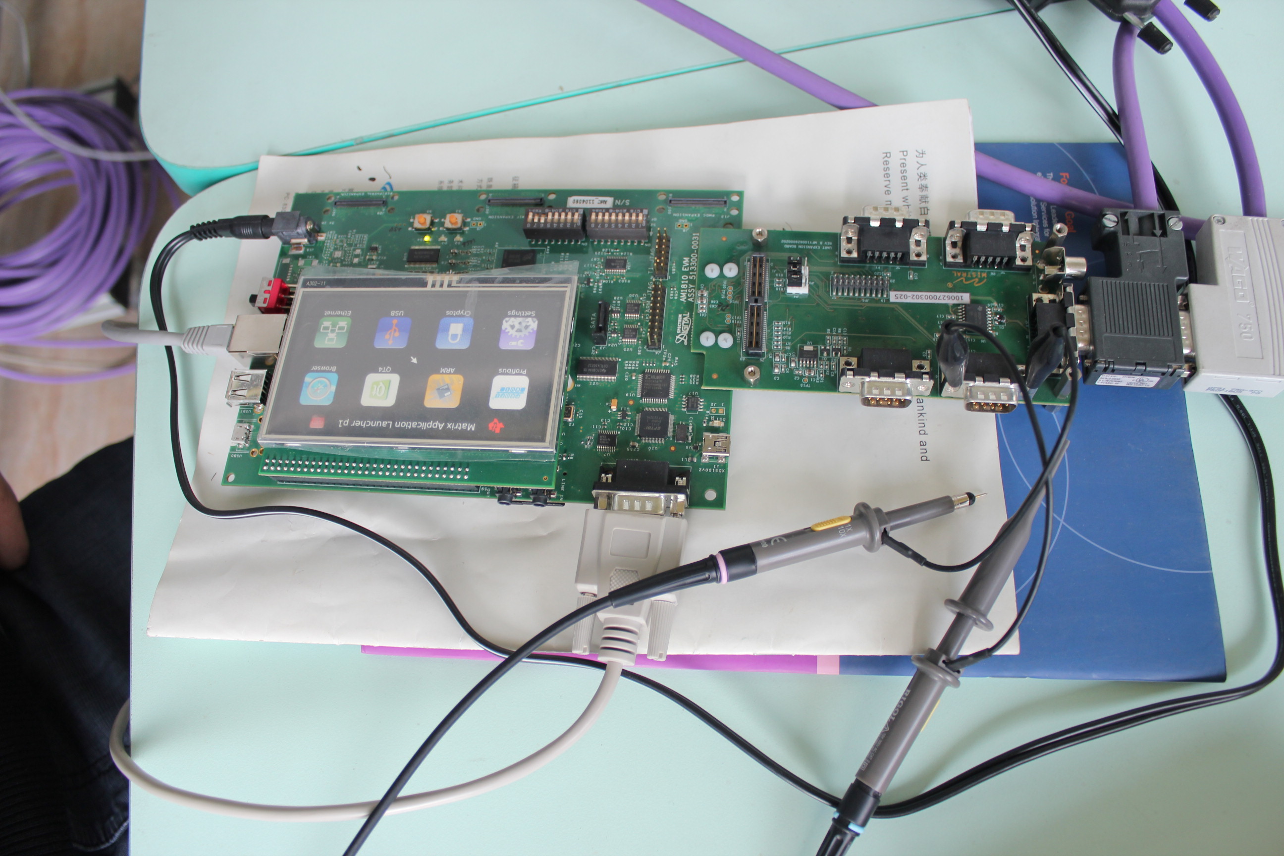
  •   Hardwares(①Mainboard: AM1810 Evaluation Module+UART EXPANSION BOARD;②DP analyser: ProfiTrace 2)
  •   Softwares (①AM1810-Linux 2.6.33.7-rt29; ②The program used for DP analyser is DPSlave_EVAL-am181x_profibus_dpslave_app-04.01.00.00; ③GSD:am181x_profibus_dpslave_app-04.01.00.00-PRU_0CDA.GSD)


2. When we use ProfiTrace as Profibus Master Station, AM1810 profibus EVM slave works normally at Baud rate of 6M(we test it by using 1byte). However, we cannot detect slave's existence at Baud rate of 12M (Shows station not exists). But AM1810 product specifcation says it can reach 12 M.


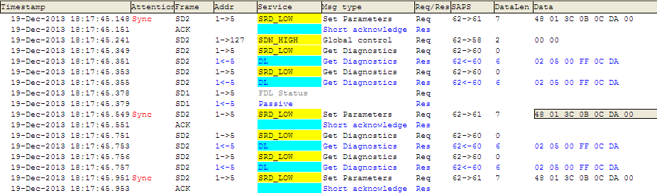
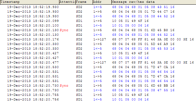
3. When we use CX1500-M310 from Beckhoff as profibus Master, and use TwinCAT to set AM 1810 profibus EVM as DP slave, cycle time=20ms, test it with 1 byte, and Baud rate 3M.

  •     when we have a stable input(only 1 byte) such as 0x06, Data Exchange shows normal.
  •     But when we have 1 byte input periodically changed, Data Exchange shows unstable and the real status as follows: 0-No error; 2-Station not exists; 8-Station not ready; 11-Physical faults. It keeps like these status

Have you ever met this situation before? This has confused us for a long time. We will appreciate a lot if you can help us to figure out this problem. Thank you! I hope you also enjoy this technical discussion.

Comment from Mr. Thomas Mauer: "However, if you are facing instability issues with high baud rates, one root cause could be missing termination resistor(s) at the end of each line. The AM1810 EVM does not have termination resistors populated (as far as I know). Does your Profibus connector has the ability to add termination resistor? The one we have do have a small switch on the connector, which will enable or disable the termination inside the connector."

Reply to Thomas: We have a simple system-a master station and a slave station. And indeed we have termination resistors at both ends of master and slave. 

  • Moving this to correct forum.
  • Hi Biser! Thank you for reminding me. Actually at first I had no idea which sub-forum I should post my questions.  Any recommendation for profibus DP AM1810? Thanks. 

    Hi I just copied it to Sitara™ Processors forum as I cannot move this post or delete this one. I hope Admin can help delete it. Thanks.

  • Hi Guotao,

    I understood from your initial forum entry that you checked the termination resistors at both ends and that they are set in your cable.

    Are you using the Profibus application which is part of the evaluation package from TI or did you create your own project / or recompiled the source code? You are also using the TI EVM with AM1810, not your own platform, right?

    I suggest to validate that the Profibus UART generates the correct baudrate. Profibus UART baudrate will be sourced by either PLL0 or PLL1 depending on your uboot/Linux/SW configuration. As a start, validate with a scope the TX response of the slave at an high baud rate, and see if the UART timing matches with selected baud rate. You can use TX_EN of ISO1176 as trigger input for the scope.

    Regards,

     Thomas

  • Hi Thomas! Nice to meet you at TI community. Yes, we are using the Profibus application which is part of evaluation package from TI. And we don't change any source code of TI AM1810 EVM. We use the original one.

    Can I understand your suggestions are more to solve the problem of "station not exists" at 12M baudrate(When we use ProfiTrace as Profibus Master Station, AM1810 profibus EVM slave)?  Actually at 6 M baudrate, system works normally and 6M is enough for us at present. It indeed can work. We are just curious why it cannot work at 12M baudrate as product specification says. But this is ok because it is less urgent. We can talk this after another problem. 

    The urgent problem is when we use CX1500-M310 from Beckhoff as profibus Master, and use TwinCAT to set AM 1810 profibus EVM as DP slave, cycle time=20ms, test it with 1 byte, and baud rate 3M(which is much smaller than 6M).  By the way, it is very popular that Beckhoff CX1500-M310 works as profibus master in wind turbine. 

    •     A: when we have a stable input(only 1 byte) such as 0x06, Data Exchange shows normal.
    •     B: But when we have 1 byte input periodically changed, Data Exchange shows unstable and the real status as follows: 0-No error; 2-Station not exists; 8-Station not ready; 11-Physical faults. It keeps like these status. 
    A means under this situation, the system can work. BUT, for B, the output changes its status among the above four status. We are wondering why? 
    I really appreciate your and your colleagues' patience as the problem is probably a little boring. Just don't hesitate to comment if you have anything that can help you understand the whole picture. I will respond you quickly. Photos or screenshots or parametres. Thank you again. 
  • Hi Guotao,

    Your problem looks really strange and we did not face such yet.

    Some suggestions to help you to find the resolution:

    a) Still a wrong (or slightly off) baudrate could cause such issue on the slave. The CX might not tolerate that slightly off baudrate while the ProfiTrace does. Measure the TX response from the slave with a scope, using TX_EN of ISO1176 as trigger, and verify the bit timing.

    b) If the slave does not receive any Profibus frame within a specific time, it will start baudrate detection again. Is the 20ms cycle time eventually triggering this timeout already? Can you set the cycle time to a faster value, e.g. 5ms or 1ms?

    c) Does a lower baudrate on CX work ok? If so, it could be related to either, a shift in baudrate or profibus stack triggering timeout.

    Hope this helps so you find the root cause.

    Regards,

     Thomas

  • Thank you, Thomas! I told your analysis and  suggestions to my colleagues yesterday morning. And they have been carrying out some tests since yesterday and the work is still going on. I will conclude it here immediately they finish tests. 

    Christmas is coming, happy Christmas in advance and best wishes to you guys. 

    Cheers!

  • Hi Thomas! According to your suggestions, my colleagues carried out 2 tests as follows:

    Test 1: 
         Test condition: 
    • 1 Master and 1 Slave; Beckhoff CX1500_M310 as Master; AM1810 as Slave; DP cable tens of metres; 1 byte input and 1 byte output at Baudrate 3M;
    • Output at 1 byte per 20ms from PLC, and then AM1810 Slave recieves the byte and sends it to Beckhoff CX master;
         Test results:
    • DP data exchange is stable when PLC program output constant <50; but DP unstable when PLC program output constant>50.
    Test 2:
         Test condition:
    • 1 Master and 1 Slave; Beckhoff CX1500_M310 as Master; AM1810 as Slave; DP cable tens of metres; 1 byte input and 1 byte output at Baudrate 9.6k-187.5k;
    • Output(Variable or a constant) at 1 byte per 200ms from PLC, and then AM1810 Slave recieves the byte and sends it to Beckhoff CX master;
         Test results:
    • At baudrate of 9.6k, 19.2k, 93.75k, and 187.5k, all show "Station not exists" and cannot communicate.
    • From realtime data, we can see it cannot reach "Set Parameters" at  baudrate of 9.6k, 19.2k, 93.75k, and 187.5k. 
    • At baudrates of 500k to 3M, it can reach "Data Exchange", and data unstability is similar. 
          2 screenshots for test 2
    Screenshot 1: DP data at baudrate of 93.7k and it is similar with 9.6k, 19.2k, and 187.5k.
    Screenshot 2: DP data exchange is unstable at baudrate of 500k and the situation is similar with 3M baudrate.
    Please help us with analyzing it and thank you very much. And don't hesitate to comment on and ask for more if there is anything ambiguous. Really appreciate your help. 
    Best regards!
    Guotao
    Also attached a file of source codes which contain AM1810 DP slave application program dp_user.c, TwinCAT configuration program and PLC program. 
  • Mr. Thomas Mauer's suggestion: 

    "Can you please measure with a scope the UART TX signal: On ISO1176/1176T:

    Measure D (UART_TXD) and set the trigger to use the rising edge of DE (UART_TX_EN). I need to see the bit timing, because I still think that this might be stilll slightly off the exact baudrate."

    Reply to Thomas: 

    AM1810 Bit-time test at several DP baudrates
    • At the baudrate of 9.6k——Standard bit time: 104μs, real value in test: 108μs, Deviation is +3.8%; 
    • At the baudrate of 500k——Standard bit time: 2μs, real value in test: 2.08μs, Deviation is +4%;
    • At the baudrate of 3M——Standard bit time: 333ns, real value in test: 347ns, Deviation is +4.2%. 
    The above data is from DP analyser-ProfiTrace2. And the test at baudrate of 500k is carried out by both DP analyserand a scope and the results are similar. 
     
    Fig-1: Scope test At baudrate of 500K.
     
    Fig-2 The whole picture of the board. 
    Your analysis is very important to us.  Thank you!
  • Hi,

    Looks like UART interface is running at 150MHz instead of 156MHz required to meet the tolerance for PROFIBUS @12MBaud as Thomas M suggested.

    See http://processors.wiki.ti.com/index.php/AM1810_Frequency_Settings_For_Profibus for more details, you can verify this by looking at UBL console message when the board starts booting. UART1 used for PROFIBUS is deriving functional clock from EMIF PLL and DDR MHz numbers shall indicate this AFAIK.

  • Hi Pratheesh Gangadhar! Thanks for your analysis which is very important for us. We had never ever thought  the problems came from UART frequency. We thought the default value is 150MHz, instead of 156MHz. With your remiding, our engineers became aware of it and calculated it thereotically. And we all think it makes sense. So now we are trying to reset the frequency and to varify the assumption. But there are so many files about Uboot settings.  

    Could you please tell us how to set frequency for UART, AM1810? Thank you! 

  • Mr Pratheesh Gangadhar's reply:

    "UBL sets up the clock and this is part of flashtool - http://processors.wiki.ti.com/index.php/AM18x_Flash_Tool_User%27s_Guide 


    For AM1810 EVM (Spectrum Digital): Execute the command “sfh_OMAP-L138.exe –targetType AM1810 –flash ubl\ubl_INTDEV0_SPI_MEM.bin u-boot.bin”.

    Make sure your DIP switch settings are in line with what is mentioned in the wiki.

    Also for Beckhoff master, can you please try with default input (8byte) and output(8 byte) configuration we provided in the PROFIBUS example if possible to begin with." 

    Response:

    After starting AM1810, the available frequencies as follows:

    carry out command: cat /sys/devices/system/cpu/cpu0/cpufreq/scaling_available_frequencies

    we get: 456000 408000 372000 300000 200000 96000

    But our Profibus-DP-UART1 needs 156 MHz as we calculated theoretically,  and the CPU frequency should be 312 MHz. So how can we handle this situation? It is a little urgent for us. But I really appreciate a lot for your quick response as I know clearly that you are on Christmas holiday now. Thank you again.


  • Hi,

    Can you please post the console logs displaying frequency (from UBL and U-boot).

    http://processors.wiki.ti.com/index.php/AM1810_Frequency_Settings_For_Profibus

    There are 2 ways to make sure 156Mhz UART clock

    (1) Variable ARM frequency : EMIF and UART on same PLL: for EVMs with DDR2

    (2) Variable EMIF frequency: ARM and UART on same PLL: , for EVMs with mDDR

    AFAIK we are using method (1) in UBL for SD EVM with DDR2.

  • AM1810 initialization passed!
    Booting TI User Boot Loader
            UBL Version: 1.65
            UBL Flashtype: SPI
    
    Starting SPI Memory Copy...
    Valid magicnum, 0x55424CBB, found at offset 0x00010000.
       DONE
    Jumping to entry point at 0xC1080000.
    
    U-Boot 2009.11 (Apr 18 2011 - 14:24:01)    
    
    I2C:   ready
    DRAM:  64 MB
    MMC:   davinci: 0
    *** Warning - bad CRC, using default environment
    
    In:    serial
    Out:   serial
    Err:   serial
    ARM Clock : 300000000 Hz
    DDR Clock : 150000000 Hz
     Error - unable to probe SPI flash.
    Net:   Ethernet PHY: GENERIC @ 0x00
    
    Hit any key to stop autoboot:  0
    reading boot.scr
    
    ** Unable to read "boot.scr" from mmc 0:1 **
    reading uImage
    
    2109660 bytes read
    ## Booting kernel from Legacy Image at c0700000 ...
       Image Name:   Arago/2.6.32+2.6.33-rt29-psp03.3
       Image Type:   ARM Linux Kernel Image (uncompressed)
       Data Size:    2109596 Bytes =  2 MB
       Load Address: c0008000
       Entry Point:  c0008000
       Verifying Checksum ... OK
       Loading Kernel Image ... OK
    OK
    
    Starting kernel ...
    
    Uncompressing Linux... done, booting the kernel.
    Linux version 2.6.33.7-rt29 (schuyler_2@neo) (gcc version 4.3.3 (Sourcery G++ Li
    te 2009q1-203) ) #1 PREEMPT RT Tue Jan 11 21:00:48 CST 2011
    CPU: ARM926EJ-S [41069265] revision 5 (ARMv5TEJ), cr=00053177
    CPU: VIVT data cache, VIVT instruction cache
    Machine: DaVinci DA850/OMAP-L138/AM18xx EVM
    Memory policy: ECC disabled, Data cache writeback
    DaVinci da850/omap-l138/am18xx variant 0x1
    Built 1 zonelists in Zone order, mobility grouping on.  Total pages: 8128
    Kernel command line: mem=32M console=ttyS2,115200n8 root=/dev/mmcblk0p2 rw rootw
    ait ip=off
    PID hash table entries: 128 (order: -3, 512 bytes)
    Dentry cache hash table entries: 4096 (order: 2, 16384 bytes)
    Inode-cache hash table entries: 2048 (order: 1, 8192 bytes)
    Memory: 32MB = 32MB total
    Memory: 28068KB available (3892K code, 338K data, 148K init, 0K highmem)
    Real-Time Preemption Support (C) 2004-2007 Ingo Molnar
    Experimental preemptable hierarchical RCU implementation.
    NR_IRQS:245
    Console: colour dummy device 80x30
    Calibrating delay loop... 149.50 BogoMIPS (lpj=747520)
    Mount-cache hash table entries: 512
    CPU: Testing write buffer coherency: ok
    DaVinci: 144 gpio irqs
    regulator: core version 0.5
    NET: Registered protocol family 16
    bio: create slab <bio-0> at 0
    SCSI subsystem initialized
    usbcore: registered new interface driver usbfs
    usbcore: registered new interface driver hub
    usbcore: registered new device driver usb
    regulator: VDCDC1: 3200 <--> 3300 mV at 3300 mV
    regulator: VDCDC2: 1750 <--> 3300 mV at 3300 mV
    regulator: VDCDC3: 950 <--> 1375 mV at 1200 mV
    regulator: LDO1: 1800 mV
    regulator: LDO2: 1150 <--> 1300 mV at 1200 mV
    pca953x 1-0020: failed reading register
    i2c-gpio i2c-gpio.1: using pins 20 (SDA) and 21 (SCL)
    Advanced Linux Sound Architecture Driver Version 1.0.21.
    Switching to clocksource timer0_1
    musb_hdrc: version 6.0, cppi4.1-dma, host, debug=0
    Waiting for USB PHY clock good...
    musb_hdrc: USB Host mode controller at fee00000 using DMA, IRQ 58
    musb_hdrc musb_hdrc: MUSB HDRC host driver
    musb_hdrc musb_hdrc: new USB bus registered, assigned bus number 1
    hub 1-0:1.0: USB hub found
    hub 1-0:1.0: 1 port detected
    NET: Registered protocol family 2
    IP route cache hash table entries: 1024 (order: 0, 4096 bytes)
    TCP established hash table entries: 1024 (order: 1, 8192 bytes)
    TCP bind hash table entries: 1024 (order: 2, 28672 bytes)
    TCP: Hash tables configured (established 1024 bind 1024)
    TCP reno registered
    UDP hash table entries: 64 (order: 0, 4096 bytes)
    UDP-Lite hash table entries: 64 (order: 0, 4096 bytes)
    NET: Registered protocol family 1
    RPC: Registered udp transport module.
    RPC: Registered tcp transport module.
    RPC: Registered tcp NFSv4.1 backchannel transport module.
    EMAC: MII PHY configured, RMII PHY will not be functional
    JFFS2 version 2.2. (NAND) © 2001-2006 Red Hat, Inc.
    msgmni has been set to 54
    io scheduler noop registered (default)
    da8xx_lcdc da8xx_lcdc.0: GLCD: Found Sharp_LK043T1DG01 panel
    Console: switching to colour frame buffer device 60x34
    Serial: 8250/16550 driver, 3 ports, IRQ sharing disabled
    serial8250.0: ttyS0 at MMIO 0x1c42000 (irq = 25) is a 16550A
    serial8250.0: ttyS1 at MMIO 0x1d0c000 (irq = 53) is a 16550A
    serial8250.0: ttyS2 at MMIO 0x1d0d000 (irq = 61) is a 16550A
    console [ttyS2] enabled
    brd: module loaded
    at24 1-0050: 32768 byte 24c256 EEPROM (writable)
    Read MAC addr from EEPROM: 00:0e:99:03:70:45
    ahci ahci: forcing PORTS_IMPL to 0x1
    ahci ahci: AHCI 0001.0100 32 slots 1 ports 3 Gbps 0x1 impl SATA mode
    ahci ahci: flags: ncq sntf pm led clo only pmp pio slum part ccc
    scsi0 : ahci
    ata1: SATA max UDMA/133 irq 67
    spi_davinci spi_davinci.1: DaVinci SPI driver in EDMA mode
    Using RX channel = 18 , TX channel = 19 and event queue = 1
    m25p80 spi1.0: non-JEDEC variant of m25p64
    m25p80 spi1.0: m25p64 (8192 Kbytes)
    Creating 4 MTD partitions on "m25p80":
    0x000000000000-0x000000040000 : "U-Boot"
    0x000000040000-0x000000050000 : "U-Boot Environment"
    0x000000050000-0x0000007f0000 : "Linux"
    0x0000007f0000-0x000000800000 : "MAC Address"
    Read MAC addr from EEPROM: ff:ff:ff:ff:ff:ff
    spi_davinci spi_davinci.1: Controller at 0xfef0e000
    console [netcon0] enabled
    netconsole: network logging started
    Initializing USB Mass Storage driver...
    usbcore: registered new interface driver usb-storage
    USB Mass Storage support registered.
    input: TPS6507x Touchscreen as /devices/platform/i2c-gpio.1/i2c-1/1-0048/input/i
    nput0
    omap_rtc omap_rtc: rtc core: registered omap_rtc as rtc0
    omap_rtc: RTC power up reset detected
    omap_rtc: already running
    i2c /dev entries driver
    Linux video capture interface: v2.00
    usbcore: registered new interface driver uvcvideo
    USB Video Class driver (v0.1.0)
    watchdog watchdog: heartbeat 60 sec
    cpuidle: using governor ladder
    cpuidle: using governor menu
    davinci_mmc davinci_mmc.0: Using DMA, 4-bit mode
    usbcore: registered new interface driver usbhid
    usbhid: USB HID core driver
    usbcore: registered new interface driver snd-usb-audio
    No device for DAI tlv320aic3x
    asoc: tlv320aic3x <-> davinci-i2s mapping ok
    mmc0: new SDHC card at address e624
    mmcblk0: mmc0:e624 SD08G 7.40 GiB
     mmcblk0:
    ALSA device list:
      #0: DA850/OMAP-L138 EVM (tlv320aic3x)
    TCP cubic registered
    NET: Registered protocol family 17
    Clocks: disable unused i2c1
    Clocks: disable unused emac
    Clocks: disable unused aemif
    Clocks: disable unused spi0
    Clocks: disable unused mcbsp0
    Clocks: disable unused mcbsp1
    Clocks: disable unused vpif
    Clocks: disable unused ecap0
     p1
    ata1: SATA link down (SStatus 0 SControl 300)
     p2 p3
    regulator_init_complete: incomplete constraints, leaving LDO2 on
    regulator_init_complete: incomplete constraints, leaving LDO1 on
    regulator_init_complete: incomplete constraints, leaving VDCDC3 on
    regulator_init_complete: incomplete constraints, leaving VDCDC2 on
    regulator_init_complete: incomplete constraints, leaving VDCDC1 on
    davinci_emac_probe: using random MAC addr: 46:72:81:13:db:19
    emac-mii: probed
    omap_rtc omap_rtc: setting system clock to 2011-01-25 15:00:19 UTC (1295967619)
    EXT3-fs (mmcblk0p2): warning: maximal mount count reached, running e2fsck is rec
    ommended
    kjournald starting.  Commit interval 5 seconds
    
    EXT3-fs (mmcblk0p2): using internal journal
    EXT3-fs (mmcblk0p2): recovery complete
    EXT3-fs (mmcblk0p2): mounted filesystem with writeback data mode
    VFS: Mounted root (ext3 filesystem) on device 179:2.
    Freeing init memory: 148K
    INIT: version 2.86 booting
    Please wait: booting...
    Starting udev
    EXT3-fs (mmcblk0p3): warning: maximal mount count reached, running e2fsck is rec
    ommended
    kjournald starting.  Commit interval 5 seconds
    
    EXT3-fs (mmcblk0p3): using internal journal
    EXT3-fs (mmcblk0p3): recovery complete
    EXT3-fs (mmcblk0p3): mounted filesystem with writeback data mode
    Remounting root file system...
    Caching udev devnodes
    Populating dev cache
    NET: Registered protocol family 10
    logger: mount: mount point /proc/bus/usb does not exist
    ALSA: Restoring mixer settings...
    No state is present for card EVM
    Unknown hardware: "tlv320aic3x" "" "" "" ""
    Hardware is initialized using a guess method
    No state is present for card EVM
    Configuring network interfaces... eth0: attached PHY driver [SMSC LAN8710/LAN872
    0] (mii_bus:phy_addr=1:00, id=7c0f1)
    ADDRCONF(NETDEV_UP): eth0: link is not ready
    udhcpc (v1.13.2) started
    Sending discover...
    PHY: 1:00 - Link is Up - 100/Full
    ADDRCONF(NETDEV_CHANGE): eth0: link becomes ready
    Sending discover...
    Sending discover...
    No lease, forking to background
    done.
    Setting up IP spoofing protection: rp_filter.
    INIT: Entering runlevel: 5
    Starting system message bus: dbus.
    Starting Dropbear SSH server: dropbear.
    Starting telnet daemon.
    Starting syslogd/klogd: done
    Starting thttpd.
    Starting Matrix GUI application.
    Hi Pratheesh Gangadhar! Thank you for your quick response. 

    As you said, the frequencies should have been 375 MHz variable for ARM, 156MHz fixed for EMIF, and 156MHz for UART with EMIF and UART on same PLL.  Am I understanding you right? 

    But when we started U-boot up, the ARM frequency whose frequency data was printed via UART onto computer screen is 300MHz, a fixed data on screen.

    How can we understand this?   Please see attached log file. 

    Thanks a lot! 

    Regards!

    Guotao

    Add up something we guessed: 

    All the time we have been using "ubl_AM1810_SPI_MEM.bin" in OMAP-L138_FlashAndBootUtils_2_31 of the developer pack. And we also tried the new version-OMAP-L138_FlashAndBootUtils_2_40. But the results are the same as the discussions above. We are wondering if it probably set a fixed 300MHz in  "ubl_AM1810_SPI_MEM.bin"? Just a guess from us. If yes, is there a ARM frequency 312 MHz UBL for us to have a try?  Thank you!

    Since we got this 1810 board, it has been confusing us for almost half a year, and we just test it as the AM1810 specification says because we trust it. But we had never thought the problem probaly comes from this level which we shouldn't have considered during our developer work. It costs us a lot of time and we are in eager to figure it out. 

  • Hi,

    Did below command work for you ? Can you share the screenshot as well

    sfh_OMAP-L138.exe –targetType AM1810 –flash ubl\ubl_INTDEV0_SPI_MEM.bin u-boot.bin

    I reviewed flasher tool package from http://sourceforge.net/projects/dvflashutils/files/OMAP-L138/

    It looks like wiki is not up to date with the package. AM1810 SPI UBL shall be "OMAP-L138\GNU\ubl\ubl_AM1810_SPI_MEM.bin"

    sfh_OMAP-L138.exe –targetType AM1810 –flash ubl\ubl_AM1810_SPI_MEM.bin u-boot.bin

    You shall use the u-boot.bin for AM1810 from SDK

  • Hi,

    Sorry  I missed your latest update.

    I cross checked the old E-mails and AM1810 SDK is validated using 2.31 version of flashtool . Did you revert switch S7 boot settings for SPI boot mode back after flashing?

    Set the boot pins to SPI1 boot mode. This is done by setting switch S7 on the AM18x EVM according to the following table:

    AM180x EVM (Logic)

    Pin# 1 2 3 4 5 6 7 8
    Position OFF OFF OFF OFF OFF OFF OFF OFF

    AM1810 EVM (Spectrum Digital)

    Pin# 1 2 3 4 5 6 7 8
    Position OFF OFF OFF OFF OFF ON ON OFF
  • For the two versions, namely, \OMAP-L138\GNU\ubl\ubl_AM1808_SPI_MEM.bin in the toolkit of OMAP-L138_FlashAndBootUtils_2_40 and \OMAP-L138\GNU\ubl\ubl_AM1808_SPI_MEM.bin in the toolkit of OMAP-L138_FlashAndBootUtils_2_31
    With the two version respectively, we used sfh_OMAP-L138.exe to refreshed SPI Flash , and after started, both showed:
    ARM Clock : 300000000 Hz
    DDR Clock : 150000000 Hz
    Well, neither of the two is what we wanted for Profibus_dpslave application because our DP couldn't work normally.
    BUT,
    We indeed figured out the problem at last. Our engineers found this file "OMAP-L138_FlashAndBootUtils_2_31\OMAP-L138\CCS\UBL_ARM\UBL_AM1810_SPI.ais" in so many files and with this, we refreshed SPI flash. After started, it showed: 
    ARM Clock : 372000000 Hz
    DDR Clock : 156000000 Hz
    And then, Profibus_dpslave works normally
    For the past several months, our engineers tried many other ways to smash the problem depicted in the original post. But we didn't manage to solve it because we had never thought the problem came from such a basic level. 
    Meanwhile, we think we should point it out that we cannot find any specified information about how to solve such problems from TI websites or technical reference manuals(maybe because AM1810 was a product years ago, and also very few users). It cost time for us to inquire to you like this and we really appreciate your help.
    After this problem, there are probably more problems on the way to develop AM1810 on profibus_dpslave application for us.
    AM1810 was developed by TI long time ago(several years ago), but we still hope to establish a connection with the engineers who ever participated in developing AM1810. If none, at least help us from your company to find the UBL source codes that match with "OMAP-L138_FlashAndBootUtils_2_31\OMAP-L138\CCS\UBL_ARM\UBL_AM1810_SPI.ais", with which we can refer to and compile. Really important for us to save more time when problems come. 
    We are really happy that our problem got handled. Thank you for your help as I know you are on Christmas holiday now. And also thank Thomas. 
    We are looking forward to your response. Happy new year in advance!
    Best regards!
    Guotao and other engineers.
  • And we also sincerely hope these posts can help AM1810 users who encounter such problems. :)

  • Hi,

    Glad that this worked for you. I have updated wiki here with your resolution. Unfortunately engineer worked on this part is no longer with us and it was difficult to track down all the details. I sincerely apologize for inconvenience caused to you - you guys really did an amazing job finding this out even though documentation was quite poor.

    Did this also solve the issues you saw with Beckhoff master? 

    In parallel as a solution I have actually recompiled UBL in flashtool package with below patch for ARM to run at 312 MHz and UART1 to run at 156MHz. (By default CFGCHIP[3].ASYNC3_CLKSRC bit is clear and clock is sourced from PLL0_SYSCLK2). But in the UBL  you just flashed this bit is set and ASYNC3 clock is sourced from  PLL1_SYSCLK2 so UART clock is independent of ARM clock...

     OMAP-L138_FlashAndBootUtils_2_40\OMAP-L138\Common\src\device.c

    #if defined(AM1808)
        // CPU(s) at 456 MHz
        status |= DEVICE_PLL0Init(0, 18, 0, 0, 0, 18, 8);
      #elif defined(AM1810)
        // CPU(s) at 312 MHz
         status |= DEVICE_PLL0Init(0, 25, 0, 1, 0, 11, 5);
      #else
        // CPU(s) at 300 MHz
        status |= DEVICE_PLL0Init(0, 24, 0, 1, 0, 11, 5);
      #endif 

  • Hi Mr. Pratheesh Gangadhar! Yes,  when we use CX1500-M310 from Beckhoff as profibus Master and AM1810 as slave, it works normally too.  But all the tests were based on sending only one byte.

    We are now testing on multiple bytes. I will update this post here once  there is any progress.

    Thank you again. 

    Last day in 2013 today, hahaha.       Happy new year! 

  • Hi, Mr Pratheesh Gangadhar!
    We tested on sending multiple bytes and we have a problem.
     
    • Test 1: ProfiTrace as Master, AM1810 DP slave, Baudrate 3M, 200 bytes data to test
    • Test 2: CX1500-M310 from Beckhoff as profibus Master, AM1810 DP slave, Baudrate 3M, 200 bytes data to test
    The results from both situation are the same as follows:

    The AM1810 DP slave can recieve 200 bytes correctly from both Masters, ProfiTrace or CX1500-M310. BUT, when AM1810 DP slave sends 200 bytes data, both Masters can only correctly recieve the 128 bytes in the front of the 200 bytes, but not for the rest bytes.
     
    Please help with analyzing it which is very important for us. Thank you very much! 
      
    Best regards!
    Guotao
  • Hi, Mr Pratheesh Gangadhar! Guess you guys are very enjoying holiday now. We have only one offwork day and really envy you guys, hahaha.


    Today we met another problem during developing a new board based on AM1810, for which we just keep several parts such as Ethernet, SD and UART2 UART1. Yes, we removed USB, SATA, Video, Audio and LCD etc. as we don't have to use them in our DP application.

    We flash the new board and the old board(AM1810 EVM) talked in original post by using  \OMAP-L138\GNU\ubl\ubl_AM1808_SPI_MEM.bin in the toolkit of OMAP-
    L138_FlashAndBootUtils_2_40, and both the boards can work normally where the frequencies show as follows:
    ARM Clock : 300000000 Hz
    DDR Clock : 150000000 Hz

    Anyway, as you know, the frequency settings are not what our team needs. Instead, we need 156 MHz DDR with ARM 375MHz or 312MHz.

    So we tried to flash the new board with "OMAP-L138_FlashAndBootUtils_2_31\OMAP-L138\CCS\UBL_ARM\UBL_AM1810_SPI.ais" which should have presented us a 156MHz
    DDR and 372 MHz ARM. But it doesn't work. At first we thought it was the hardware's problem as we developed it by ourself, but the new board functions well as mentioned above. Thus we don't think hardware problem exists. 

    Please help us analyse where the problems come. Thank you very much.


    The following information should be useful for your analysis.

    For new board, we flash Uboot by using sfh_OMAP-L138 -targetType AM1810 -flash UBL_AM1810_SPI.ais u-boot.bin
    -p COM3
    Operation windows
    ---------------------------------------------------

    --
    TI Serial Flasher Host Program for OMAP-L138
    (C) 2011, Texas Instruments, Inc.
    Ver. 1.67
    -----------------------------------------------------


    [TYPE] UBL and application image
    [UBL] UBL_AM1810_SPI.ais
    [APP IMAGE] u-boot.bin
    [TARGET] AM1810
    [DEVICE] SPI_MEM

    Attempting to connect to device COM3...
    Press any key to end this program at any time.

    (AIS Parse): Read magic word 0x41504954.
    (AIS Parse): Waiting for BOOTME... (power on or reset target now)
    (AIS Parse): BOOTME received!
    (AIS Parse): Performing Start-Word Sync...
    (AIS Parse): Performing Ping Opcode Sync...
    (AIS Parse): Processing command 0: 0x58535901.
    (AIS Parse): Performing Opcode Sync...
    (AIS Parse): Loading section...
    (AIS Parse): Loaded 8696-Byte section to address 0x80000000.
    (AIS Parse): Processing command 1: 0x58535901.
    (AIS Parse): Performing Opcode Sync...
    (AIS Parse): Loading section...
    (AIS Parse): Loaded 820-Byte section to address 0x800021F8.
    (AIS Parse): Processing command 2: 0x58535906.
    (AIS Parse): Performing Opcode Sync...
    (AIS Parse): Performing jump and close...
    (AIS Parse): AIS complete. Jump to address 0x80000000.
    (AIS Parse): Waiting for DONE...
    (AIS Parse): Boot completed successfully.

    Waiting for SFT on the OMAP-L138...

    Flashing UBL UBL_AM1810_SPI.ais (9732 bytes) at 0x00000000

    100% [ ████████████████████████████████████
    Image data transmitted over UART.

    100% [ ████████████████████████████████████
    UBL programming complete


    Flashing application u-boot.bin (173012 bytes)

    100% [ ████████████████████████████████████
    Image data transmitted over UART.

    100% [ ████████████████████████████████████
    Application programming complete


    Operation completed successfully.

    ==============================================================================
    Booting with TI UBL
    Device OPP (300MHz, 1.2V)
    Flash Type : WinBond Flash

    We added: The process ends here and it doesn't finish Uboot start and ARM frequency isn't 372MHz, but 300MHz(It should have been 372MHz).

    =============================================
    However, we tried the same process on AM1810 EVM board, the old one and everything goes on well.

    Booting with TI UBL
    Device OPP (372MHz, 1.2V)
    Flash Type : WinBond Flash


    U-Boot 2009.11 (Apr 18 2011 - 14:24:01)

    I2C: ready
    DRAM: 64 MB
    MMC: davinci: 0
    In: serial
    Out: serial
    Err: serial
    ARM Clock : 372000000 Hz
    DDR Clock : 156000000 Hz
    Net: Ethernet PHY: GENERIC @ 0x00

    Hit any key to stop autoboot: 0
    reading uImage

    2109660 bytes read
    .....

  • Hi,

    >The AM1810 DP slave can recieve 200 bytes correctly from both Masters, ProfiTrace or CX1500-M310. BUT, when AM1810 DP slave sends 200 bytes data, both Masters can only correctly recieve the 128 bytes in the front of the 200 bytes, but not for the rest bytes.

    This indeed is a bug in the firmware, but good news is that we found a fix for the same 8640.libprofibus_dpslave.zip


    Please try with this new evaluation library and let us know the results

  • Hi,


    (1) Can you try below patch for OMAP-L138_FlashAndBootUtils_2_40\OMAP-L138\Common\src\device.c to add 312 MHz ARM clock and 156MHz UART1 clock support? I assume you can recompile UBL from OMAP-L138_FlashAndBootUtils_2_40 package using CCS.  If not please let me know

    OMAP-L138_FlashAndBootUtils_2_40\OMAP-L138\Common\src\device.c

    #if defined(AM1808)
        // CPU(s) at 456 MHz
        status |= DEVICE_PLL0Init(0, 18, 0, 0, 0, 18, 8);
      #elif defined(AM1810)
        // CPU(s) at 312 MHz
         status |= DEVICE_PLL0Init(0, 25, 0, 1, 0, 11, 5);
      #else
        // CPU(s) at 300 MHz
        status |= DEVICE_PLL0Init(0, 24, 0, 1, 0, 11, 5);
      #endif

    (2)What is the SPI flash used in your board ? Can you read the ID of the flash? Is this something as shown below

    #define WINBOND_ID_W25Q64              0x4017

    AM1808 EVM and AM1810 EVM has got different SPI flashes AFAIK. U-boot and Linux kernel auto detects the same but UBL has got some hard coding I think. So please fix this as well in your version of UBL accordingly

    For eg:- OMAP-L138_FlashAndBootUtils_2_40\OMAP-L138\Common\src\device_spi.c

    const SPI_MEM_ParamsObj DEVICE_SPI_MEM_params =
    {
      SPI_MEM_TYPE_FLASH,
      24,                     // addrWidth
      256,                    // pageSize
      #ifdef AM1810
      4096,                   // sectorSize
      #else
      0,                   // sectorSize
      #endif
      64*1024,                // blockSize
      8*1024*1024             // memorySize           
    };

  • Hi Pratheesh Gangadhar! Thank you for your reply. 

    Refering to "The AM1810 DP slave can recieve 200 bytes correctly from both Masters, ProfiTrace or CX1500-M310. BUT, when AM1810 DP slave sends 200 bytes data, both Masters can only correctly recieve the 128 bytes in the front of the 200 bytes, but not for the rest bytes."

     Response: Yes, the patch works and 200 bytes can be recieved from AM1810 DP slave correctly. Our next plan is to try 244 bytes and I will update the post here once it works.

    Refering to the new board we are developing based on AM1810. 

    Response:

    1) The compile environment for UBL files has already been built and we finished compiling files for OMAP-L138_FlashAndBootUtils_2_40. With this, we flashed AM1810 UBL and Uboot, but after started, the results as follow: 

    ARM Clock : 300000000 Hz
    DDR Clock : 150000000 Hz


    2, We want to alter ARM frequency from 300MHz to 372MHz, DDR's frequency from 150MHz to 156MHz; and thus we modified OMAP-L138\Common\src\device.c shown as below:
    #if defined(AM1808) // CPU(s) at 456 MHz
    status |= DEVICE_PLL0Init(0, 18, 0, 0, 0, 18, 8);
    #elif defined(AM1810) // CPU(s) at 372 MHz
    status |= DEVICE_PLL0Init(0, 30, 0, 1, 0, 11, 5); //2014.01.03
    #else // CPU(s) at 300 MHz
    status |= DEVICE_PLL0Init(0, 24, 0, 1, 0, 11, 5);
    #endif

    We managed to recompile it, but when we flashed the board, the process was stuck in this status"Waiting for SFT on the OMAP-L138…" (We provided the detailed process at the end of this post)

    We are wondering if there is any other place that has to be modified accordingly? Such as "// Timings for DDR2 at 132 MHz
    status |= DEVICE_ExternalMemInit(0x00000047, 0x08934832, 0x204929C9, 0x0C12C722, 0x00000406, 0x00000000);" Is it a need to modify this?

    Please have a look. Thanks a lot!

    Attached the detailed process:


    C:\cygwin\home\OMAP-L138_FlashAndBootUtils_2_40\OMAP-L138\GNU>
    sfh_OMAP-L138 -targetType AM1810 -flash .\ubl\ubl_AM1810_SPI_MEM.bin u-boot.bin -p COM3
    -----------------------------------------------------
    TI Serial Flasher Host Program for OMAP-L138
    (C) 2014, Texas Instruments, Inc.
    Ver. 1.67
    -----------------------------------------------------


    [TYPE] UBL and application image
    [UBL] .\ubl\ubl_AM1810_SPI_MEM.bin
    [APP IMAGE] u-boot.bin
    [TARGET] AM1810
    [DEVICE] SPI_MEM
    [SPI Block] 0


    Attempting to connect to device COM3...
    Press any key to end this program at any time.

    (AIS Parse): Read magic word 0x41504954.
    (AIS Parse): Waiting for BOOTME... (power on or reset target now)
    (AIS Parse): Read invalid BOOTME string.
    (AIS Parse): Boot aborted.
    Booting SFT failed. Trying again (you may need to reset the target)...
    (AIS Parse): Read magic word 0x41504954.
    (AIS Parse): Waiting for BOOTME... (power on or reset target now)
    (AIS Parse): BOOTME received!
    (AIS Parse): Performing Start-Word Sync...
    (AIS Parse): Performing Ping Opcode Sync...
    (AIS Parse): Processing command 0: 0x58535901.
    (AIS Parse): Performing Opcode Sync...
    (AIS Parse): Loading section...
    (AIS Parse): Loaded 8676-Byte section to address 0x80000000.
    (AIS Parse): Processing command 1: 0x58535901.
    (AIS Parse): Performing Opcode Sync...
    (AIS Parse): Loading section...
    (AIS Parse): Loaded 124-Byte section to address 0x800021E4.
    (AIS Parse): Processing command 2: 0x58535901.
    (AIS Parse): Performing Opcode Sync...
    (AIS Parse): Loading section...
    (AIS Parse): Loaded 752-Byte section to address 0x80002260.
    (AIS Parse): Processing command 3: 0x58535906.
    (AIS Parse): Performing Opcode Sync...
    (AIS Parse): Performing jump and close...
    (AIS Parse): AIS complete. Jump to address 0x80000000.
    (AIS Parse): Waiting for DONE...
    (AIS Parse): Boot completed successfully.

    Waiting for SFT on the OMAP-L138...