This thread has been locked.

If you have a related question, please click the "Ask a related question" button in the top right corner. The newly created question will be automatically linked to this question.

Capturing BT.656 640x480 progressive video by VPIF fails

Other Parts Discussed in Thread: OMAP-L138

I am trying to capture BT.656 640x480 progressive video from OV7690 sensor on OMAP-L138 board. OV7690 connected by 8 data lines and input clock.

It seems that OV7690 sensor outputs <sav> <1280 bytes Y/C mux> <eav> <272 bytes blank> per line. It is always frame 0, sav/eav seems to be correct. It seems that sensor outputs 480 lines, then it outputs nothing for 4 lines time (there is no sav/eav), then 22 lines with VSync indication, then nothing for 6 lines time (again, there is no sav/eav), giving total 512 lines with 10 lines skipped.

I have configured VPIF to:

  .eav2sav = 280-8,
  .sav2eav = 1280,
  .l1 = 1,
  .l3 = 22,
  .l5 = 502,
  .vsize = 502,

I am not sure about IMGOFFSET value, should it be 640 or 1280? Also, not really sure about VSYNC->L1 offset, but I have no VBI.

I have tried both Y/C mux (intended behavior) and non-Y/C mux mode (just for debugging), but neither works.

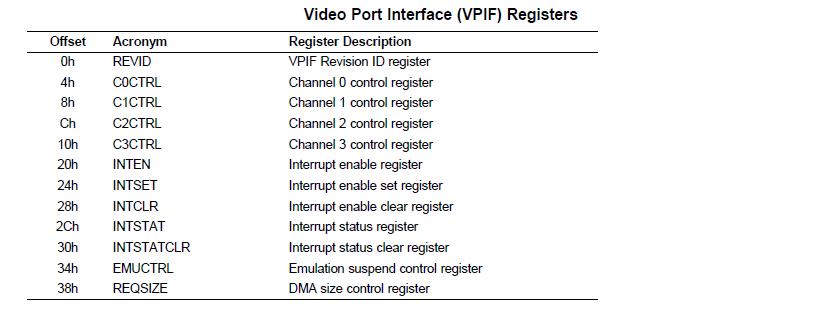
I have the following VPIF registers values configured for Y/C mux mode:

00:  4c080a01 00001409 00000000 00000000
10:  00000000 00000104 00000000 00000000
20:  00000011 00000011 00000000 00000010
30:  00000000 00000001 00000080 00000000
40:  c6000000 00000000 c604b000 00000000
50:  00000000 00000000 00000000 00000000
60:  00000000 00000500 00000000 01100500
70:  00010016 01f60000 00000000 000001f6
80:  00000000 00000000 00000000 00000000

I get ERROR interrupt once per frame, and no FRAME interrupts. I get code 0x104 in 0x14 VPIF register, but I cannot find specification on it. Is it generally available?

I have the following VPIF registers values configured for non-Y/C mux mode (debugging only):

00:  4c080a01 00001401 00000000 00000000
10:  00000000 00000000 00000000 00000000
20:  00000011 00000011 00000000 00000000
30:  00000000 00000001 00000080 00000000
40:  c6000000 00000000 c604b000 00000000
50:  00000000 00000000 00000000 00000000
60:  00000000 00000500 00000000 01100500
70:  00010016 01f60000 00000000 000001f6
80:  00000000 00000000 00000000 00000000

I get no interrupts this way.

Having said that, I have the following questions:

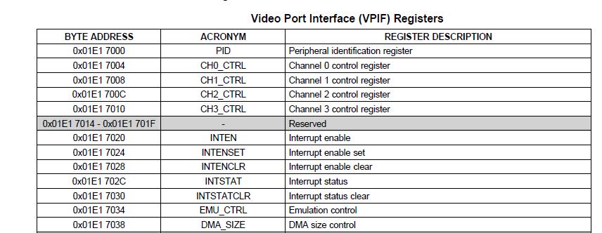
1) Is there documentation regarding register 0x14 of VPIF?

2) What is the right value for IMGOFFSET and Lx for Y/C mux in progressive mode?

3) Is there any problem with 10 skipped lines in VPIF stream?

Thank you in advance.

  • Welcome to the TI E2E forum. I hope you will find many good answers here.
    In addition you can find some details through the TI.com documents and the TI Wiki Pages.
    Be sure to search those for helpful information and to browse for the questions others may have asked on similar topics.

    VPIF:

    Up to 2 Video Capture Channels (Channel 0 and Channel 1)

    • Two 8-bit Standard-Definition (SD) Video with embedded timing codes (BT.656)

    Up to 2 Video Display Channels (Channel 2 and Channel 3)

    • Two 8-bit SD Video Display with embedded timing codes (BT.656)

    I could not see 0x14 register address used by VPIF. Please possible mention the register name.
    For your reference, see mentioned here some of the registers are used by VPIF.

    Note: Progressive video only uses top-field buffers, the address offset per line of data is equal to hofst (CnIMGOFFSET = hofst). When capturing 10-bit or 12-bit video in the raw capture mode, the offset per line of data is doubled because of bit padding.

    Video Receive:
    VPIF channels 0 and 1 are used for video receive.

    For BT.656 video, luminance (Y) and chrominance (C) values are multiplexed into a single byte-stream on
    one channel (either channel 0 or channel 1).
    The Y/C multiplex function for BT.656 video is enabled by setting the YCMUX bit in the channel control
    registers CnCTRL. The YCMUX bit must be the same for both channels 0 and 1.

    Video Transmit:
    VPIF channels 2 and 3 are used for video transmit.

    For BT.656 video, luminance (Y) and chrominance (C) values are multiplexed into a single byte-stream on
    one channel (either channel 2 or channel 3).
    The Y/C multiplex function for BT.656 video is enabled by setting the YCMUX bit in the channel control
    registers CnCTRL. The YCMUX bit must be the same for both channels 2 and 3.

  • Thanks for answer.

    I cannot access reg 0x14 description in documentation, it is stated 'reserved' as you pointed. But I can see that it's value is changing, and I guess that it might report exact error code when ERROR interrupt occurs - unfortunately, I could not find any way to distinguish:

    • For channels 0 or 1:
    – Internal buffer overflow
    – Length of EAV2SAV or SAV2EAV is not the same as the configured value
    – Bit error detected on 4th field of TRC

    I got value 0x104 for channel 0, value 0x208 for channel 1 and value 0x30c when I attach two sensors with setup described above. So I guess it indicates some errors, and I wonder if there is any documentation on that.

    As for CnIMGOFFSET I got really messed up by documentation. I have 640 pixels per line, that is 1280 bytes of Y/C multiplexed data. I use progressive mode and frame capture.

    Specification says:

    Address offset per line of data in each top- or bottom-field buffer is equal to hofst × 2
    (CnIMGOFFSET = hofst × 2)

    In Y/C mux mode, the actual address offset is CnIMGOFFSET × 2.

    My guess is that CnIMGOFFSET should be 640, so actual offset per line will be 1280 bytes. But I do not get how (CnIMGOFFSET = hofst x 2) is applied here - hofst is probably in bytes, and should be 1280, so I get confused with CnIMGOFFSET value.