This thread has been locked.

If you have a related question, please click the "Ask a related question" button in the top right corner. The newly created question will be automatically linked to this question.

TMS320C5505 SPI_CS (active low) active to SPI_CLK active parameter

Hi all,

I have a question about the SPI interface on the C5505 DSP that we are redesigning. The DSP operates as master on the SPI interface. I have screen shot the section of the datasheet I am looking at below:
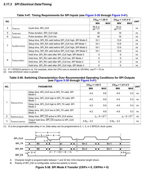
   

I am interested in parameter 2, which is the chip select asserted to SPI_CLK edge. The datasheet seems to show a maximum value, or at least it looks like it. Is there a minimum value for this, i.e. the minimum time between the chip select being asserted before the SPI_CLK edge. We are looking at putting a buffer in between this chip select and a slave device on this bus, and I need to understand what the absolute minimum time from chip select being asserted I have until the clock is driven out, so I can account for any delays in the buffer while not violating set up time in the slave device?

 Thanks in advance for your help.

  • Hello Allan,

     The datasheet  indicates the delay time between the SPI CS to the SPI CLK active time:

     The  delay time is calulated based on the spi clk cycle time ("tc") & the Data delay that is programmable to 0, 1, 2 or 3 SPI clocks.  The delay time will vary based on the configuration that is between 0 to 3.

    Also  'with respect to tc' -> which is SPI cycle time, datasheet has already specified the minimum time.

    Hope the above information helps you to according calculate the timings.. based on your slave requirements.

    Regards

     Vasanth


  • Hi Vasanth,

    Thanks for the quick reply.

    Are you referring to parameter 2 in table 5-48, which is tc-8+D? I have seen this, but from what I can tell this is the MAX delay time. i.e. worst case delay until SPI_CLK appears after the SPI_CS is asserted.

    I am looking for the MIN delay time - How long is SPI_CS guaranteed to be low before the SPI_CLK edge. This is the equivalent to the set up time at the slave device. 

    I wish to buffer the SPI_CS, and my concern is I add in delay that causes, at the slave device, for the SPI_CLK edge to happen before SPI_CS is asserted.

    Thanks, 

    Alan.

  • Hello, was there ever a conclusion related to the minimum value of parameter td(SPICS-SCLK)? In my application, I must ensure that the CS setup time is met before CLK is issued (for the slave device I am connecting to), so this minimum value is important to me as well.

  • Hi,

    As mentioned in the SPI User guide, The SPI module automatically delays the first clock edge with respect to the activation of the SPI_CSn pin by half a SPI_CLK cycle plus a system clock cycle. Additional clock delay cycles can be added using the data delay bits (DDn) of SPIDCR1 and SPIDCR2.

    The data delay field should be programmed such that the chip select setup requirement of the slave is met. A 1-bit data delay is recommended when running the SPI_CLK at frequencies greater than 2.5 MHz; otherwise a 0-bit data delay can be used.

    For further information please refer user guide in below mentioned link.

    sprufo3

    Hope the above information helps.