This thread has been locked.

If you have a related question, please click the "Ask a related question" button in the top right corner. The newly created question will be automatically linked to this question.

Operating C5515 in low power mode

Other Parts Discussed in Thread: TMS320C5515

Hello,

I am in immediate need for suggestion from any TI engineer on the low power mode of C5515 DSP

UserGuide suggests me to use Power Configurations RTC only,IDLE 3,2 ,Active modes,so in this context i have the following questions

Q1: What are the wake up times for the three power saving modes i did not see any info regarding this

Q2: For IDLE 3,2 there when some procedures are mentioned as step ,are there no steps to be followed for RTC mode?

Q3: What will be memory values after wakeup ? will they be changed ? (memory values after different wakeup's RTC,Idle3,2)

Q4: If Wakeup time is in our hands how to increase or decrease it ? at a cost of power consumption ?

Q5: What are the aftermath or effects after different Wakeup's?

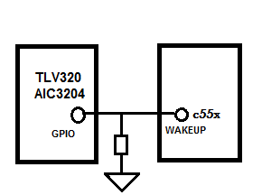
Q6: What is the circuitry for wakeup signal(in my case i have AIC3204 interfaced to the DSP,AIC3204 INT1 will be connected to the wakeup signal further which will generate  a 2ms pulse up on an interrupt)after wakeup is inserted a active high signal what should i do ? should i have to use a toggle switch for this ? is wakeup should to tiedup always ? totally confused with wakeup

PS: If there are any Sample codes showing these power saving modes please suggest them as soon as possible

  • A1: The wakeup time is specified in data manual under "Wake-Up From IDLE Elec trical Data/Timing". RTC only depends on the application code executed.

    A2: Refer to this page for information: http://processors.wiki.ti.com/index.php/C55xx_RTC_ONLY_MODE_SUPPORT

    A3: If internal LDOs are used to power device in RTC-Only mode, then all LDOs were off and re-powered. Power up sequence is followed and ROM code is loaded. All internal memory are back to default after reset. While Idle3 & 2 do not power down domains. As long as reset is not used to exit, memory content should be preserved. Table 1-31 in apps note shows the various exit methods.

    A4: Shorter boot code.

    A5: This all depends on the method used to exit and what codes are in the ISR.

    A6: No sure how to answer you. Maybe refer to C5515 EVM schematic, JP5 chooses either pull down (2-3)  to disable wakeup or push button (1-2) to generate a high pulse to wakeup. INT0 & INT1 are low active. The min pulse width is 30.5us in data manual.

    Regards.

  • A1: The wakeup time is specified in data manual under "Wake-Up From IDLE Elec trical Data/Timing". RTC only depends on the application code executed.

    yes its clear in that so my doubt on this is resolved

    A3: If internal LDOs are used to power device in RTC-Only mode, then all LDOs were off and re-powered. Power up sequence is followed and ROM code is loaded. All internal memory are back to default after reset. While Idle3 & 2 do not power down domains. As long as reset is not used to exit, memory content should be preserved. Table 1-31 in apps note shows the various exit methods.

    literally RTC MODE is a mode which will run the code at very low speed arround 32.76Khz freq is that right ?

    so now when a wakeup pulse is asserted the wakeup pin must be tied low there after isn't it ?,as i have said the interrupt from AIC3204 will last 2ms for WAKEUP it requires only 2ms its fine then 

    now i need a circuitry which would help me to achieve this  

    A4: Shorter boot code.

    shorter boot code ? what do you mean ?

    i will say my scenario,where before going to sleep i have no job but as soon as i wakeup i have heavy work like initialization of encoder and more importantly changing the clock to 45Mhz etc,

    A5: This all depends on the method used to exit and what codes are in the ISR.

    can i write an isr  for wakeup ? is that possible i am thinking that while running in RTC mode i have to run the code of monitoring the wakeup status ,as soon as dsp wakesup i have to go for doing my work like enabling clock to high rate and doing jobs faster , is my perception right ?

    A6: No sure how to answer you. Maybe refer to C5515 EVM schematic, JP5 chooses either pull down (2-3)  to disable wakeup or push button (1-2) to generate a high pulse to wakeup. INT0 & INT1 are low active. The min pulse width is 30.5us in data manual.

    this example particularly does the manual wakeup , my particular case is a case where wakeup is asserted by a external device how to tackle this

    more importantly i want a suggestion on which will be helpful and most power reducing

    using a 'wakeup pin  based wakeup from  RTC only  mode 'or an 'Interrupt(INT0,1) based wakeup - IDLE mode' ,i personally see RTC ONLY mode seems promising in power it will be more help ful if you answer my queries 

  • Well, if you are just considering power, then it is easy to conclude from Table 1-31 in System User's Guide that RTC only mode is better than IDLE3 since all power domians are still on in IDLE3 mode.

    Hope this help.

    Regards.

  • i have tried to use the wakeup pin like this,thought of configuring GPIO for interrupt 1

    even though no where with codec chip and also c55x iam not using this interference ,but this particular configuration repeatedly resetting my c55x and restarting the device after a span of time

  • This sounds like glitches on WAKEUP pin. Have you probed with scope?

    Regards.

  • Steve Tsang said:

    This sounds like glitches on WAKEUP pin. Have you probed with scope?

    yes this was some improper soldering,now i have a different problem,when the c5515 enters in to RTC only mode the wakeup can be done through rtc interrupt and also wakeup interrupt,but when i program RTC power management register to disable the power domains right after power downing them it gets stuck and never wokeup

    to test i have put a toggle LED routine  in the RTC_ISR,right after power down in RTC only mode the LED never glown ,does the program status was dead here ?

    the RTC and Wakeup are configured to make it wakeup but still it never woke up why so ?

    what is the proper wakeup sequence ?

  • Hi,

    I am facing a similar issue when I wake up my device from RTC only mode using the RTC alarm. I am trying to toggle the  LEDs in the ISR. But all that happens at the alarm time is that all the LEDs glow up and none of my ISR instructions are executed.

    I am using TMS320C5515 eZdsp kit and making the device run in RTC only mode. When I do not switch off the LDO and BG in the RTCPMGT my ISR executes are desired but when when I switch off the ISR is not executed.

    Can you please share with me your ISR. Is there are sequence to be followed for waking up the device?


    Steve,

    You did mention that the device can be woken up only using th WAKEUP pin by setting the pin high for at least   30.5us. But, I do find that the deivce can be woken from RTC Alarm interrupt if the internal LDOI are powered up. 


    Also to mention, in RTC ISR I am configuring my PLL and IO ports before executing the toggling sequence.

    Thank in advance.

    Richard


  • Hi Richard

    How did you wakeup by RTC Alarm?   I wrote following code to set RTC interrup and power.

        asm(" *port(#0x1924) = #0x8022 "); //Alarm, EXTINTEN,  second periodic interrupt are enabled
        asm(" *port(#0x1930) = #0x0006 "); //WU_DIR input & LDO & BG shutdown

    When I start up system,  I found the Led is flashing in every second.  And the electric current of system is shocking.

    But DSP still can not wakeup. 

    How did you do it?

    Thanks

    William Zhu

  • Hello,

    If you shutdown the LDO and BG then the only wake to wake up the DSP core is through the wakeup pin. You cannot wake up the DSP core through RTC alarm as the power to the core is disconnected by shutting down the LDO and BG.

    I had a suggestion from TI support that you could connect the RTC alarm interrupt to the wake up pin through hardware. But, for my project that wasn't a feasible solution so I did not proceed with it.

    Richard