This thread has been locked.

If you have a related question, please click the "Ask a related question" button in the top right corner. The newly created question will be automatically linked to this question.

DM355 CCDC data routing to iPipe

Hello,

First Question:

We have the DM355 and I have output from our MT9V032 (752x480 VGA) camera.  :-)  But, the way I obtained video is by:

Working: CCDC -> RAW to SDRAM -> Ipipe IF -> Ipipe -> YUV422 to SDRAM -> OSD Video Window -> LCD Screen

Not working/Desired: CCDC -> IpipeIF -> Ipipe -> YUV422 to SDRAM -> OSD Video Window -> LCD Screen

Basically, I want the CCDC to not have to write RAW data to SDRAM.  I believe this is unnecessary and another "jump"/"layover" not needed.  Whenever I set the iPipeIF.CFG register INPSCR to select data input to 0-CCD Controller (instead of 1-From SDRAM (raw data)), all l get a big gray "choppy" screen (which is sensitive to CCDC input light/dark).  But it is all gray and I see no major output.

Question:

1) What else needs to be taken into consideration when you change the IpipeIF from SDRAM Raw to CCDC direct input?  I don't understand what else would need modification.

2) Is there any example code of routing data from the CCDC directly to the ipipe?  I am currently using the example:

~/dvsdk_2_00_00_22/PSP_02_00_00_140/examples/dm355/ipipe/

ipipe_config.c, etc...

3) Will direct data from the CCDC to the iPipe fix this issue?

Second Question:

My output in the "working" case looks like there is "wavy" lines throughout.  I am more than willing to give you all my registers and give as much detail as I can about the sensor.  We had to sign a NDA for details, but basic info I believe I can share.

Question:

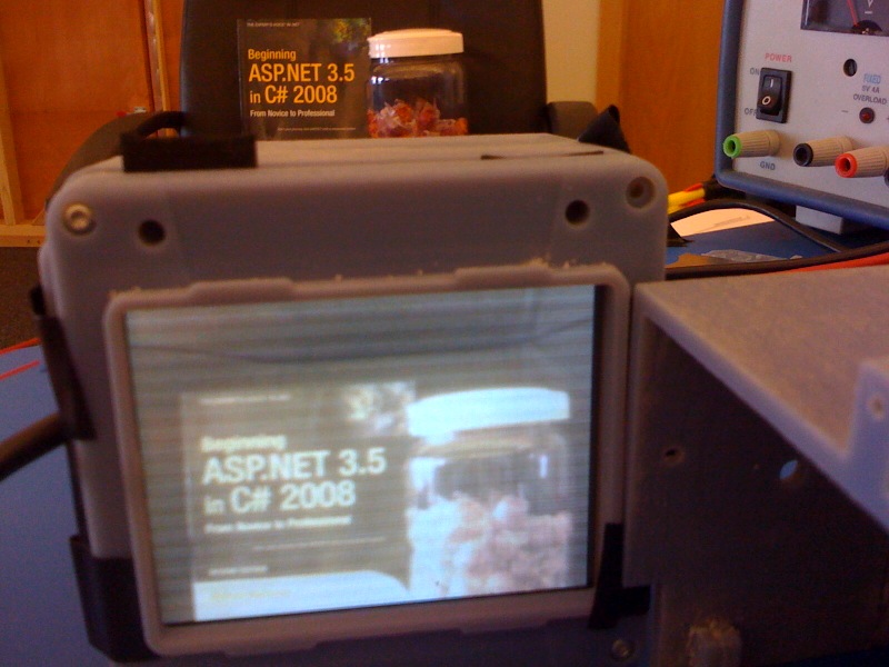
1) What registers/considerations should be looked at to try to fix the "overscanning"/"wavy" lines??  The picture below is a pretty good representation of what is happening.

Please see the picture attached:

  • Aside from IPNSRC = 0 you want to have CFG.CLKSEL = 1.  I do not believe we have any sample source code showing direct path from CCD to IPIPE (without using SDRAM), although the hardware is certainly capable of this.  

    wavy lines could be due to very slight video timing problem; it can also be due to the way the pixel data is stored in DDR2 (some data may be lost, but less likely).  Finally, even less likely, this could be due to DDR2 bandwidth limitations (although this usually shows up as random white noise, not what you are seeing).  Are you enabling all video and OSD windows?  If so, you can try disabling one or more to see if the issue goes away; this will allow us to trouble-shoot a little deeper.

  • Juan,

    Thank you very much for your response!  No luck yet...I do have a few questions though:

    1. The VPFE datasheet states CFG.CLKSEL "This register is available when INSPSRC = 1 or 3.  Should code "0" when IPSRC = 0 or 2".  The CLKDIV (which divides the VPSS clk when CLKSEL=1) states "This register is available when CLKSEL = 1".  Do you mean that CLKSEL should be set to PCLK instead?

    We already have the CLKSEL set to '0'. and we tried setting it to '1' with a proper setting to divide VPSS clk--no luck.  When routing CCDC data directly to the iPipe we get dark screen which looks like "1 pixel" repeated over the whole resolution of the resizer output window.  It is light sensitive...so the CCDC is giving data. 

    2. When in CCDC to iPipe only mode is the actual hardware signal WEN signal needed?  Our CCDC (Mt9v032) does not have a WEN signal.  We are using the DM355.CAM_WEN signal as GIO83.  We have GIO83 connected to our camera's OE (OE is an input to the camera).  Does the dm355 need the WEN signal toggling during valid frames?  We could mod the board to force the camera to always be enabled (camera OE enabled).  Then set the dm355 to use CAM_WEN and tie this pin active.  Does this sound valid?

    Any examples (schematics) on how to connect the CAM_WEN/CAM_VD/CAM_HD signals?  We have the leopardboard schematics which do almost exactly what we are currently doing...which is not working...

    We have looked at the TI Schematics and see that the CAM_WEN (VDIN_WEN) goes to a multiplexer and is not connected.  I believe that the signal would be "floating".

    Is the method of CCDC->SDRAM->iPipe->SDRAM the main way most users are implementing designs?  Have you heard of others doing CCDC->iPipe->SDRAM?  Is anyone else going from CCDC-iPipe??  If not, we will stay with the extra SDRAM layover.

    Thank you,

    Tim Liebau


  • 1)  you are correct, CLKSEL should be set to 0 (PCLK) instead.  It is interesting that you are seeing data which is sensitive to light; this likely means we are close.  If you can perhaps place a paper of a solid color (Red, Green, Yellow...) in front of the camera lens and then see what you get on the output (hex data), we may be able to find out what is happening.  The pixel data byte order may be swapped, or perhaps cut off, or saturated in some fashion. 

    2) Our video input port is pretty flexible; when it comes to video timing for a frame, DM355 can accept external timing information via VD, HD, and CAM_WEN pins...or it can generate its own internal video timing (register field VHDHEN =1 ); therefore, it is not absolutely necessary to have CAM_WEN pins connected.  However, if you are using this ping as GIO83, then I am curious how you are driving this output (input to camera); are you controlling this via software?

    Unfortunately, CCD-> IPIPE path is not supported by our Linux drivers; customers such as yourself often take our drivers and add support for such paths, but they do not always report back if they were successful; therefore I do not know if anyone has implemented this data-path yet.  But we do validate our hardware to make sure it supports what is expressed on our data-sheet, hence I am pretty confident the path does work in hadrware.

  • Hi Tim,

    Have you solved this problem yet? Can you provide a dump of your CCDC, IPIPEIF, and IPIPE registers?